
Turn on suggestions
Auto-suggest helps you quickly narrow down your search results by suggesting possible matches as you type.
Showing results for
Please log in to access translation
Turn on suggestions
Auto-suggest helps you quickly narrow down your search results by suggesting possible matches as you type.
Showing results for
Community Tip - Have a PTC product question you need answered fast? Chances are someone has asked it before. Learn about the community search. X
- Community
- Creo+ and Creo Parametric
- 3D Part & Assembly Design
- Line Driven Pattern
Translate the entire conversation x
Please log in to access translation
Options
- Subscribe to RSS Feed
- Mark Topic as New
- Mark Topic as Read
- Float this Topic for Current User
- Bookmark
- Subscribe
- Mute
- Printer Friendly Page
Line Driven Pattern
Aug 05, 2014
01:31 PM
- Mark as New
- Bookmark
- Subscribe
- Mute
- Subscribe to RSS Feed
- Permalink
- Notify Moderator
Please log in to access translation
Aug 05, 2014
01:31 PM
Line Driven Pattern
Folks,
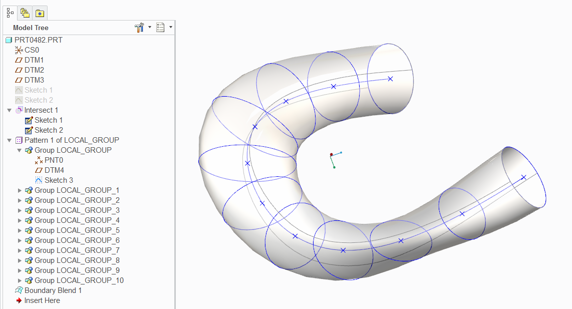
I have a duct I am trying to define in a fairly controlled manner.
I have done it thusly:
- It follows a specific centerline curve.
- It varies from an ellipse at one end to a circle (ellipse with Rmajor = Rminor) at the other.
- I created a curve.
- Made some points and datums on the curve.
- Created elippses on each datum using the point as a ref, varied Rmajor and Rminor manually per a spreadsheet
Then used a Boundary Blend to create the duct surface.
Pretty happy with the result.
But... It is not exactly parametric.
I was thinking of trying to use a Pattern, but cannot seem to find a way to change Rmajor/Rminor along the curve.
I did find that pattern along a curve drives the initial pattern nicely, adjusting the "section angle" to remain normal to the curve.
But cant seem to find a parameter which tells the sketch which pattern instance it is on, which could then be used to change Rmajor/Rminor
Can this be done in ProE?? Or am I chasing my tail?
Thanks
-ANdy
This thread is inactive and closed by the PTC Community Management Team. If you would like to provide a reply and re-open this thread, please notify the moderator and reference the thread. You may also use "Start a topic" button to ask a new question. Please be sure to include what version of the PTC product you are using so another community member knowledgeable about your version may be able to assist.
Labels:
- Labels:
-
General
10 REPLIES 10
Aug 05, 2014
01:40 PM
- Mark as New
- Bookmark
- Subscribe
- Mute
- Subscribe to RSS Feed
- Permalink
- Notify Moderator
Please log in to access translation
Aug 05, 2014
01:40 PM
Welcome to the forum, Andrew.
Why not a sweep/Blend with individual sections?
Or are you talking about simplifying the sections that you want to blend using a pattern?
As for what I learned just recently, a table pattern may just fit your bill. You don't even need points and datums along your curve.
Give us an image of what you are trying to accomplish.
Aug 05, 2014
01:49 PM
- Mark as New
- Bookmark
- Subscribe
- Mute
- Subscribe to RSS Feed
- Permalink
- Notify Moderator
Please log in to access translation
Aug 05, 2014
01:49 PM
Antonoius
So, I did use a boundary blend connecting 11 individual sections.
This was not a huge amount of work, but if want to change the area vs length curve, I have to change Rmaj/Rminor maually in 11 sketches. Not a huge problem, but not parametric.
I am looking at a table pattern, but that does not seem to allow me to create a pattern along a curve.
The local sketch plane has to turn to stay normal to the driving curve. So my table would now need to define the XY offset to stay on the curve, And somehow a rotation such that the sketch is normal to the curve. The first bit seems doable, but the rotation seems problematic.
I guess I am looking for the exposure of a parameter which tells the sketch which pattern instance it is and I can then use that parameter to set rmin/max locally.
Thanks
Andy
Aug 05, 2014
01:49 PM
- Mark as New
- Bookmark
- Subscribe
- Mute
- Subscribe to RSS Feed
- Permalink
- Notify Moderator
Please log in to access translation
Aug 05, 2014
01:49 PM
Antonoius
So, I did use a boundary blend connecting 11 individual sections.
This was not a huge amount of work, but if want to change the area vs length curve, I have to change Rmaj/Rminor maually in 11 sketches. Not a huge problem, but not parametric.
I am looking at a table pattern, but that does not seem to allow me to create a pattern along a curve.
The local sketch plane has to turn to stay normal to the driving curve. So my table would now need to define the XY offset to stay on the curve, And somehow a rotation such that the sketch is normal to the curve. The first bit seems doable, but the rotation seems problematic.
I guess I am looking for the exposure of a parameter which tells the sketch which pattern instance it is and I can then use that parameter to set rmin/max locally.
Thanks
Andy
Aug 05, 2014
02:05 PM
- Mark as New
- Bookmark
- Subscribe
- Mute
- Subscribe to RSS Feed
- Permalink
- Notify Moderator
Please log in to access translation
Aug 05, 2014
02:05 PM
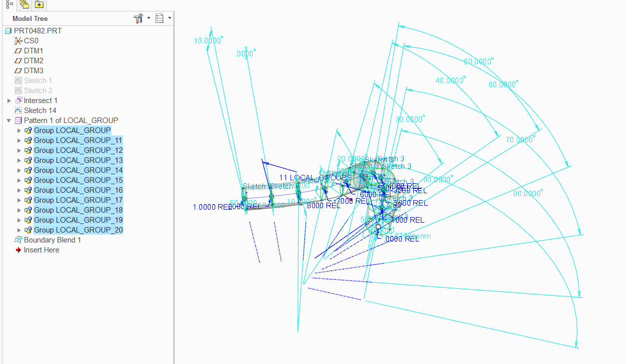
You are right about the rotation if the curve is 3D.
There are a few tricks that helps the table pattern.
1: group items so you have access to more values in the table.
2: points along a curve can be patterned based on ratio or value.
3. you might be able to provide a horizontal/vertical reference for each instance using a line that projects in the sketch. Haven't tried that yet, but as long as the line is not normal to the sketch or intersect the rotation origin, it will remain available.
This is the boundary blend version... 3 variables in the table.
As for area... you will need to create a relation to manage that. Not a problem, this can be done to the pattern feature after the fact.
Yes, you can do this fully parametrically... depending on your definition of parametric, of course. However, I suggest you want to maintain perimeter rather than area. This can be controlled in your sketch using perimeter dimension and varying the R-maj or R-min.
Aug 05, 2014
02:16 PM
- Mark as New
- Bookmark
- Subscribe
- Mute
- Subscribe to RSS Feed
- Permalink
- Notify Moderator
Please log in to access translation
Aug 05, 2014
02:16 PM
yep, worked like a charm...
If you have the full version of Creo 2.0 or 3.0, I can upload the file for your review.
Aug 05, 2014
02:40 PM
- Mark as New
- Bookmark
- Subscribe
- Mute
- Subscribe to RSS Feed
- Permalink
- Notify Moderator
Please log in to access translation
Aug 05, 2014
02:40 PM
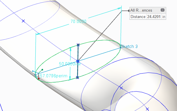
the only thing to be aware of is that the variable dimension does not update from one to the next. The starting ellipse is 50x50... when it gets to 70, the variable is actually about 24.4201... but it simply report the value form the original sketch. So be careful about using this in calculations.
Aug 05, 2014
03:37 PM
- Mark as New
- Bookmark
- Subscribe
- Mute
- Subscribe to RSS Feed
- Permalink
- Notify Moderator
Please log in to access translation
Aug 05, 2014
03:37 PM
Thank you very much.
This is just what I am looking for. The leap was in making the Group.
I actually was able to dimension to % curve
Got a nice surface.
Thanks again
-Andy
Aug 05, 2014
03:46 PM
- Mark as New
- Bookmark
- Subscribe
- Mute
- Subscribe to RSS Feed
- Permalink
- Notify Moderator
Please log in to access translation
Aug 05, 2014
03:46 PM
Happy to help 
Aug 05, 2014
04:27 PM
- Mark as New
- Bookmark
- Subscribe
- Mute
- Subscribe to RSS Feed
- Permalink
- Notify Moderator
Please log in to access translation
Aug 05, 2014
04:27 PM
Since the subject of area vs perimeter was brought up, here is a quick comparison.
This is the relation added to the area section... the deviation is due to part accuracy (default)
/* area=pi*a*b <= formula for ellipse area
/* b=area/(pi*a) <= formula if area and R-maj is known
area=pi*50*50 <= area for a round ellipse with R50
sd4=area/(pi*sd0) <= sd0 is R-Maj; sd4=R-min
Maintaining perimeter is easy as this is maintained with each sketch. For assigning area, you would include the formula above in the feature's relations of both R-min and R-maj for each sketch. Any value put in the table will have a unique corresponding ID that can be used in relations.
This is useful for hydro-formed tubing as compared to deformed tubing.


