Turn on suggestions
Auto-suggest helps you quickly narrow down your search results by suggesting possible matches as you type.
Showing results for
Please log in to access translation
Turn on suggestions
Auto-suggest helps you quickly narrow down your search results by suggesting possible matches as you type.
Showing results for
Community Tip - Need to share some code when posting a question or reply? Make sure to use the "Insert code sample" menu option. Learn more! X
- Community
- Creo+ and Creo Parametric
- 3D Part & Assembly Design
- Re: Logic behind Sketch Orientation?
Translate the entire conversation x
Please log in to access translation
Options
- Subscribe to RSS Feed
- Mark Topic as New
- Mark Topic as Read
- Float this Topic for Current User
- Bookmark
- Subscribe
- Mute
- Printer Friendly Page
Logic behind Sketch Orientation?
Oct 06, 2015
09:26 AM
- Mark as New
- Bookmark
- Subscribe
- Mute
- Subscribe to RSS Feed
- Permalink
- Notify Moderator
Please log in to access translation
Oct 06, 2015
09:26 AM
Logic behind Sketch Orientation?
This is a very simple situation; one that is fairly easy to work around, but I don't understand the need for extra mouse clicks.
I'm wondering if I'm just missing something.
ZW was the CAD software we used to use. In ZW you could click on the view you needed to sketch from and when choosing the datum that was parallel to the screen the placement of the sketch did not move. For sanity's sake I like to view a sketch from it's logical direction.
I'm wishing the same thing was possible in Creo (Perhaps it is, but I've not got this to work with the FRONT VIEW sketch)
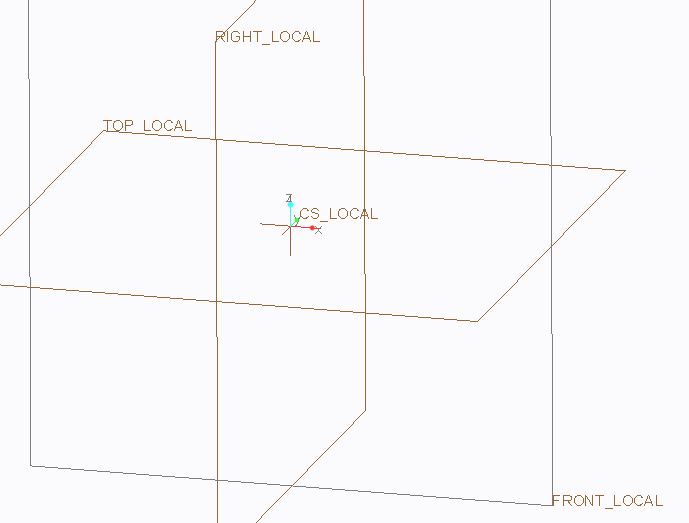
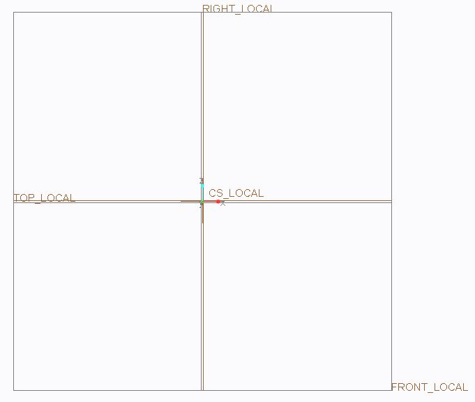
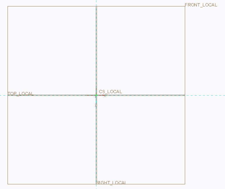
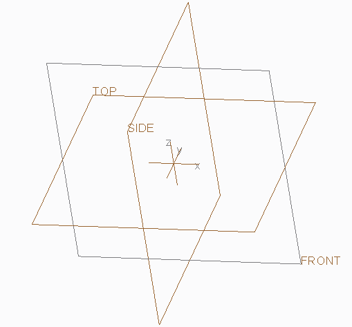
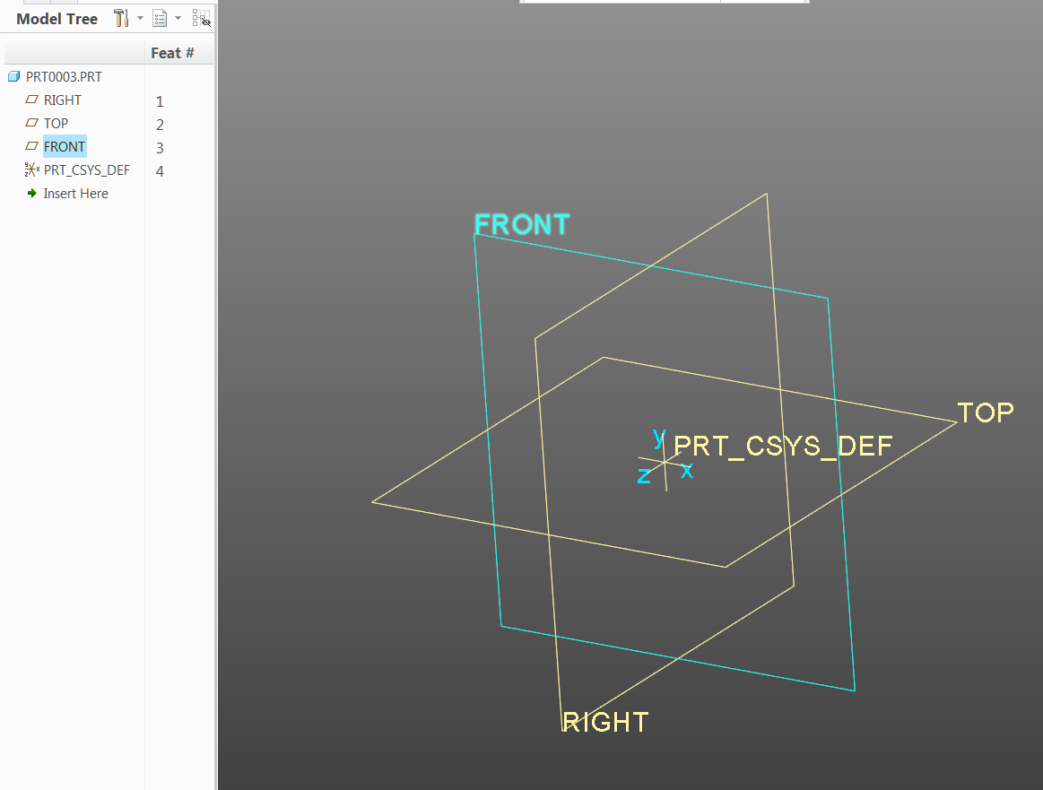
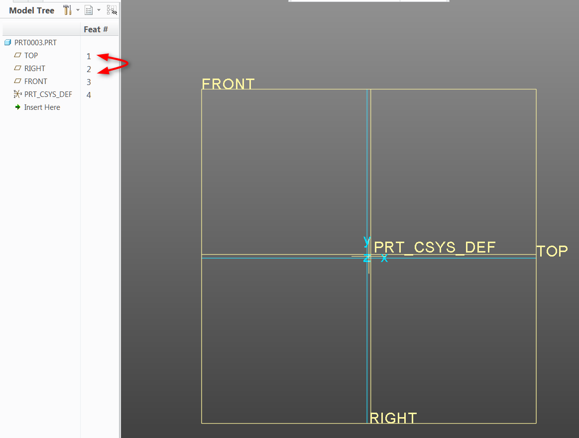
My views and datums are not the standard Creo orientation. I've changed this to the World View Coordinate System.
This is how the view orientation looks lined up with the datums.
Let's say I want to make a sketch from the Front View.
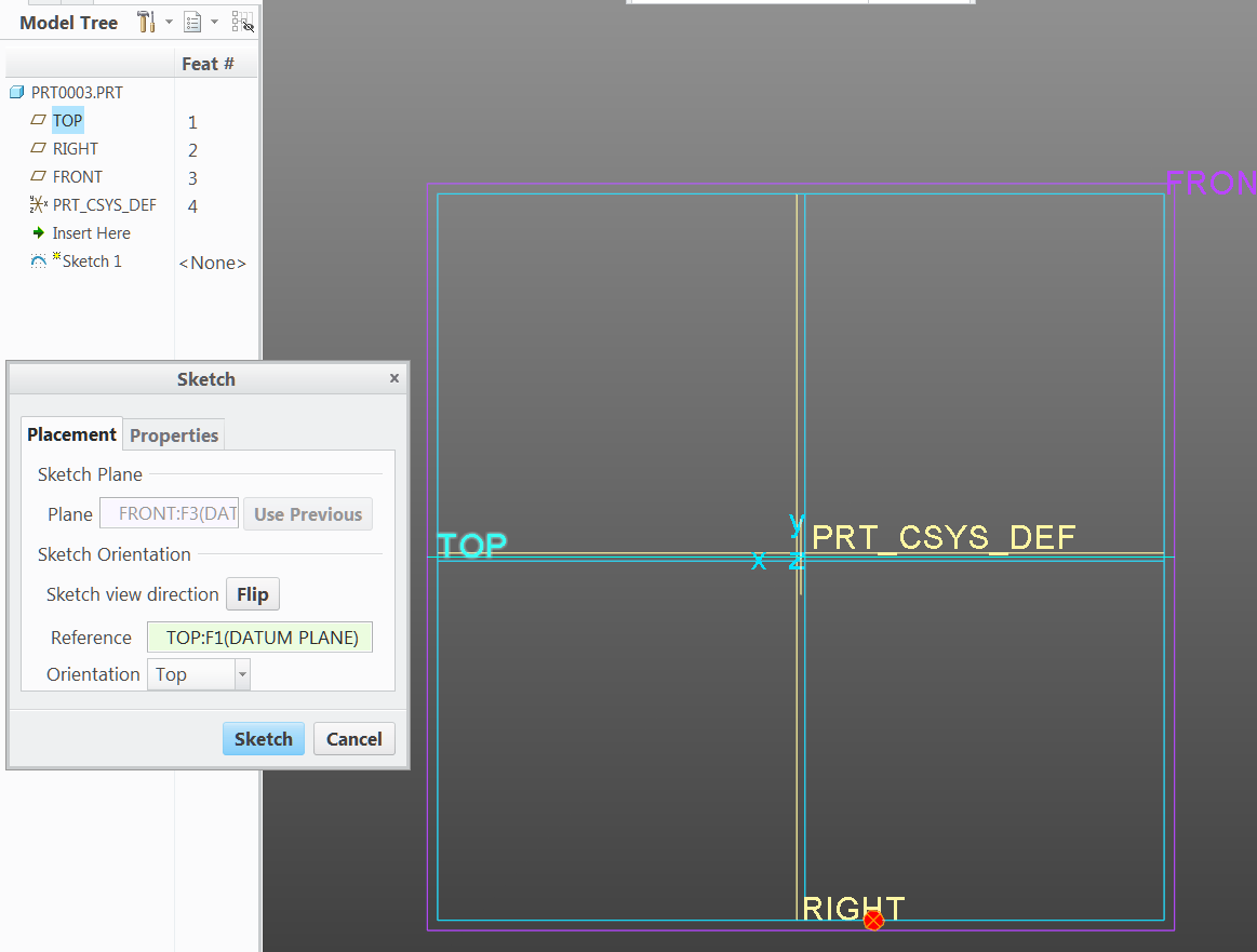
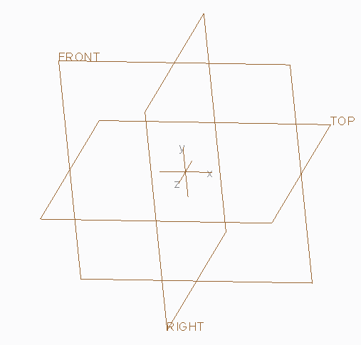
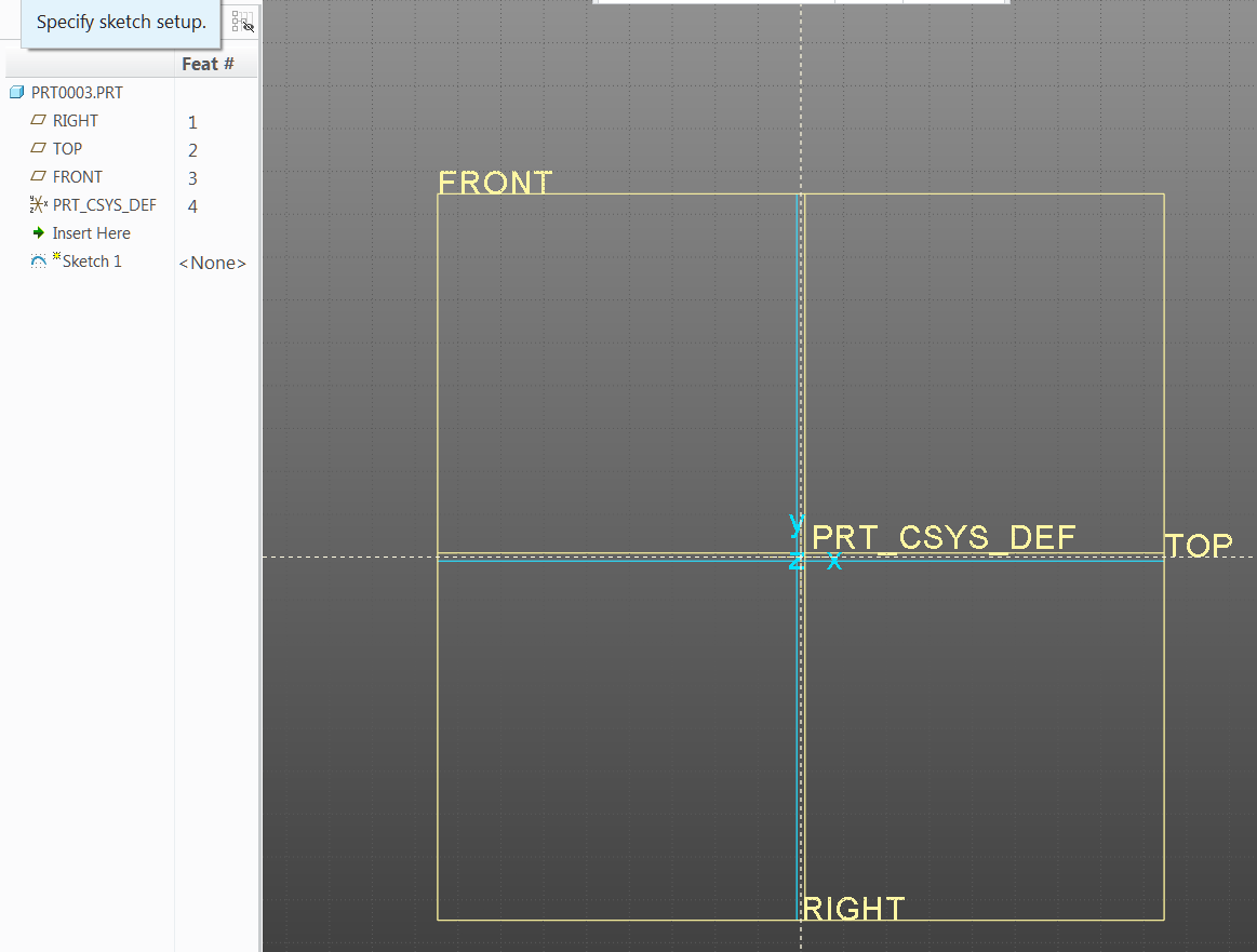
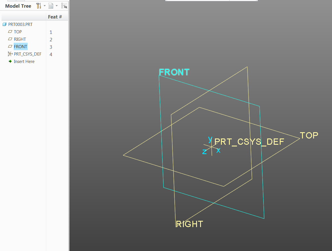
1) I set up to be in the Front View.
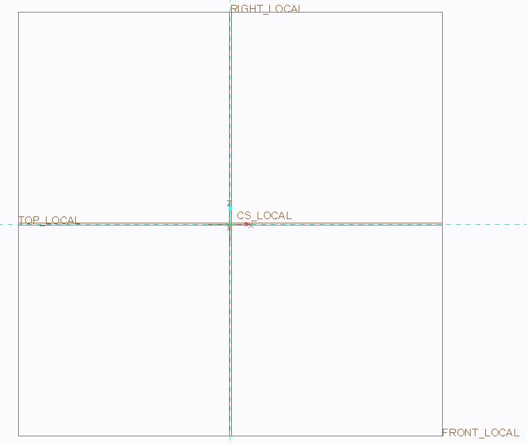
2) I pick the Front Plane. BELOW IS THE ORIENTATION I WANT TO END UP WITH.
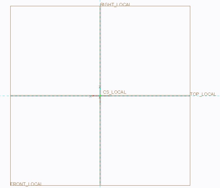
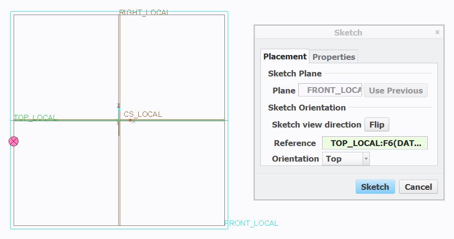
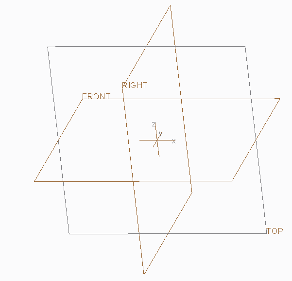
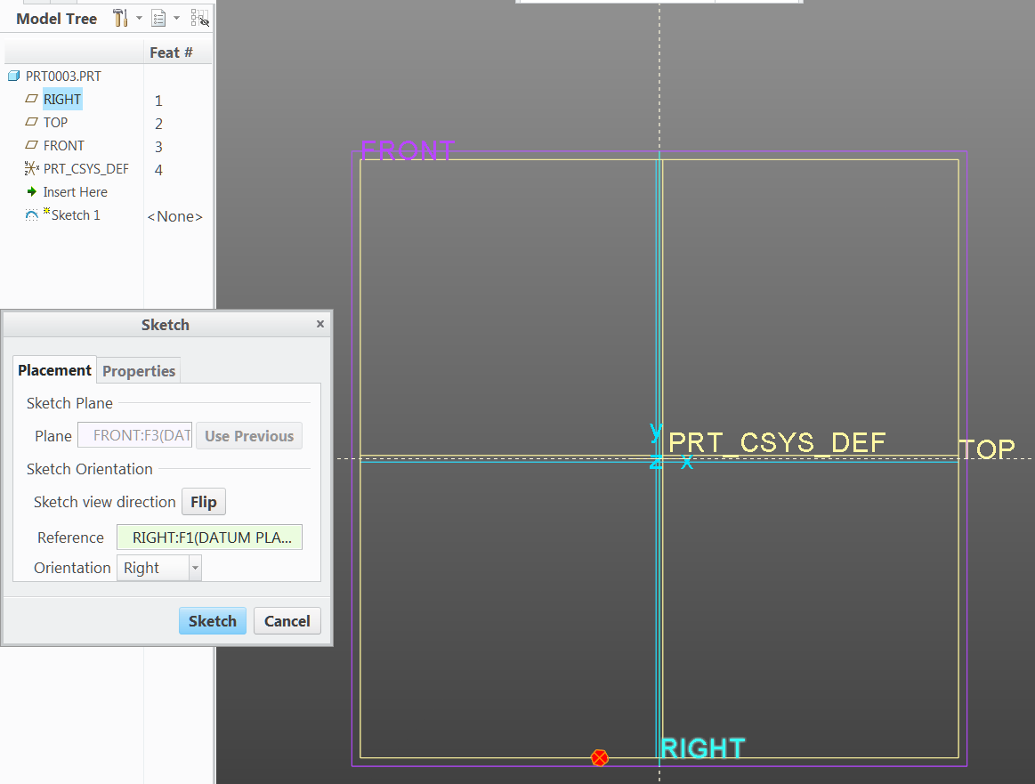
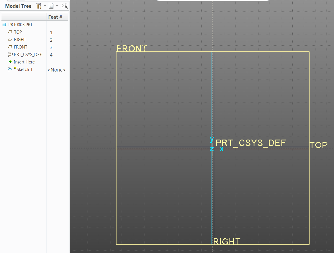
When I do 3) select Sketch it completely flips the view orientation as shown.
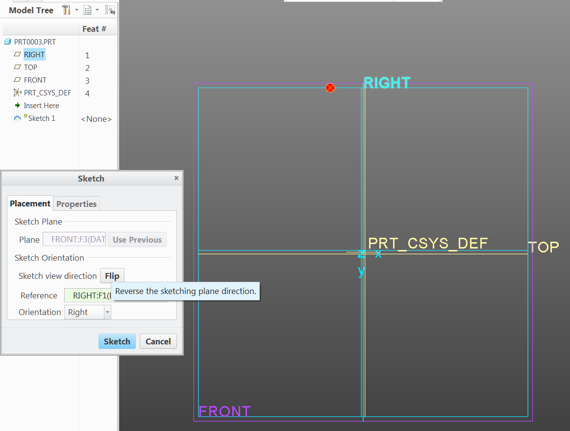
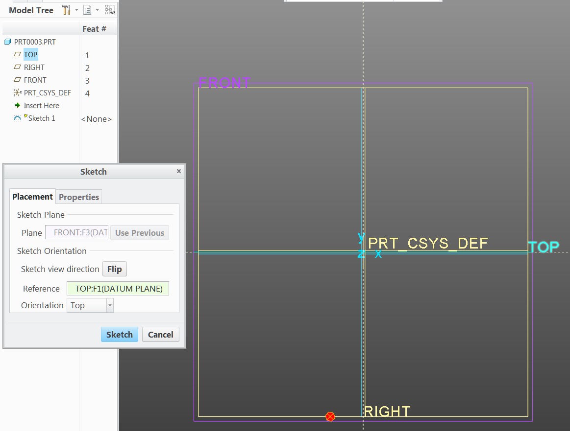
I can get this back to the orientation I WANT TO END UP WITH but it takes a couple additional sketch orientation steps. I need to Flip Section
After this I need to Flip Sketch Plane and it is back to the ORIENTATION I WANT TO END UP WITH.
As stated above this only doesn't work with the FRONT VIEW. If I go into a template that I didn't change to World View all 3 main directions work with the sketch orientation.
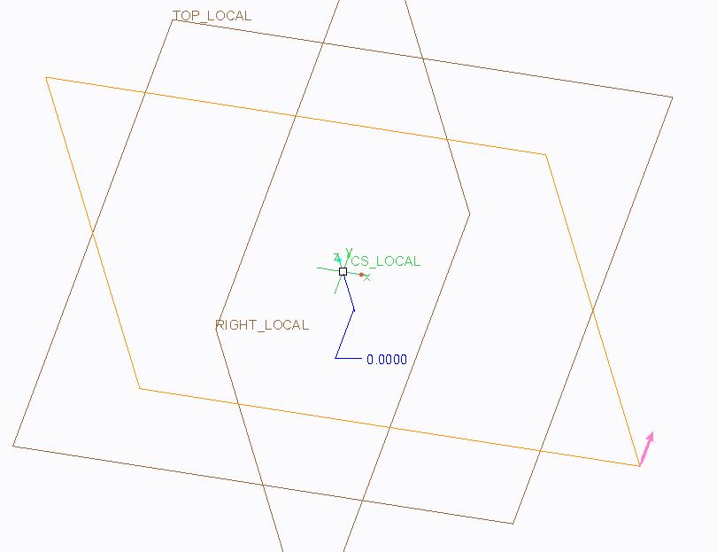
I can get the FRONT VIEW sketch to fall in it's true position if I don't select the Front Datum prior to selecting sketch and flip the arrow so it is pointing down instead of up as follows.
Everything else appears to be correct with my View and Datum orientations, they act like they should.
Does anyone have an idea of how I could by default get the arrow to be flipped to aim into the screen without having to select this manually? I think this would prevent the flipping and rotating of the FRONT VIEW.
Labels:
- Labels:
-
2D Drawing
27 REPLIES 27
Oct 06, 2015
09:40 AM
- Mark as New
- Bookmark
- Subscribe
- Mute
- Subscribe to RSS Feed
- Permalink
- Notify Moderator
Please log in to access translation
Oct 06, 2015
09:40 AM
It's hard to tell specifically but I think what is happening is your preferred sketch orientation is on the "back" side of the front_local plane.
Planes have a front and back that you can see with the brown? and black? color (used to be easy to tell red and yellow).
I believe Creo is trying to assume you want to sketch on the "front" side of the front_local plane. I'm not sure there is a solution. Possibly a mapkey to do the selections for you based on names of the planes.
Oct 06, 2015
10:06 AM
- Mark as New
- Bookmark
- Subscribe
- Mute
- Subscribe to RSS Feed
- Permalink
- Notify Moderator
Please log in to access translation
Oct 06, 2015
10:06 AM
Stephen: It appears the Normals point the direction they should. I am seeing all my normals Brown in the positive direction.
The only thing mixed up so far appears to be the Sketch Orientation.
Oct 06, 2015
09:48 AM
- Mark as New
- Bookmark
- Subscribe
- Mute
- Subscribe to RSS Feed
- Permalink
- Notify Moderator
Please log in to access translation
Oct 06, 2015
09:48 AM
You should be able to edit the definition of the FRONT_LOCAL plane and flip the "normal direction". That should take care of it.
Oct 06, 2015
09:55 AM
- Mark as New
- Bookmark
- Subscribe
- Mute
- Subscribe to RSS Feed
- Permalink
- Notify Moderator
Please log in to access translation
Oct 06, 2015
09:55 AM
Dave: I like this idea but when I Edit Definition to the Datum it appears the Normal is in the correct orientation without flipping it.
Oct 06, 2015
10:00 AM
- Mark as New
- Bookmark
- Subscribe
- Mute
- Subscribe to RSS Feed
- Permalink
- Notify Moderator
Please log in to access translation
Oct 06, 2015
10:00 AM
Are you sure that's the right way? The normal shows the 'front' of the plane; this is opposite to the default direction of viewing on that plane. In different words, when you sketch on a plane the Normal arrow will be pointing at you, out of the screen.
Oct 06, 2015
10:06 AM
- Mark as New
- Bookmark
- Subscribe
- Mute
- Subscribe to RSS Feed
- Permalink
- Notify Moderator
Please log in to access translation
Oct 06, 2015
10:06 AM
This is correct. The arrow points out of the screen when sketching. Just try it and start a sketch and it should orient correctly.
Oct 06, 2015
10:52 AM
- Mark as New
- Bookmark
- Subscribe
- Mute
- Subscribe to RSS Feed
- Permalink
- Notify Moderator
Please log in to access translation
Oct 06, 2015
10:52 AM
You are right Dave; this does work if you flip the Front Datum orientation.
I like the fact that this works however I'm a little hesitant to make this change unless I'm sure it won't mess up anything else that I've done.
This would have it's normal pointing in a negative direction whereas the other primary datums are pointing in the positive direction.
I will definitely consider this if it wouldn't create other issues.
Oct 06, 2015
12:11 PM
- Mark as New
- Bookmark
- Subscribe
- Mute
- Subscribe to RSS Feed
- Permalink
- Notify Moderator
Please log in to access translation
Oct 06, 2015
12:11 PM
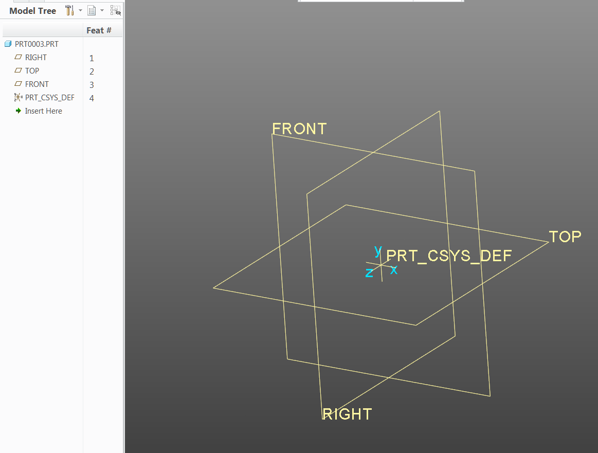
Johnathan: The picture in which I am showing the normal direction is showing brown because I am doing an Edit Definition.
The very 1st picture shows the Front Datum with a Grey color.
All 3 main datums point positive in the positive quadrant.
Oct 07, 2015
04:10 AM
- Mark as New
- Bookmark
- Subscribe
- Mute
- Subscribe to RSS Feed
- Permalink
- Notify Moderator
Please log in to access translation
Oct 07, 2015
04:10 AM
Yep, so your planes all have their 'front' in the +ve axis direction.
What about your views? From your pictures, it seems you want Front to be viewing on the 'back' of that plane - i.e. the +ve Y-axis direction is into the screen. Is this the case for your other named views - are they defined with the +ve X- and Z-axes pointing into the screen?
Also:
Paul Imm wrote:
... if I don't select the Front Datum prior to selecting sketch...
I always use the explicit Sketch Placement dialogue (i.e. never select a plane before sketching), otherwise you're leaving Creo to guess what you want to be your top / right / whatever orientation reference. It's good practice in Creo to always know exactly what you're referencing, for every feature.
In our start part we've got round this problem completely by calling the planes X_0, Y_0 and Z_0, and having six views called X_Front, X_Rear, Y_Front, etc.  - it's very hard to say what the front, top or right of a shaft, gear or bearing is in any case!
Oct 07, 2015
09:17 AM
- Mark as New
- Bookmark
- Subscribe
- Mute
- Subscribe to RSS Feed
- Permalink
- Notify Moderator
Please log in to access translation
Oct 07, 2015
09:17 AM
Jonathan:
Yes every datum looks into the positive quadrant. If I do an extrude I would expect it's positive to project into the positive quadrant.
As far as views go; if I place an object on a table if I look down on the object it would be considered the Top View. If I look at the closest edge surface from the front of the table it would be considered the Front View. If I look at the closest edge surface from the right of the table it would be considered the Right View.
The way views and datums are set up you always would look at what is closest to you and an extruded sketch would always extrude into the screen.
I'm sorry if my terminology is deficient. I'm not sure what +ve would refer to.
Oct 07, 2015
10:58 AM
- Mark as New
- Bookmark
- Subscribe
- Mute
- Subscribe to RSS Feed
- Permalink
- Notify Moderator
Please log in to access translation
Oct 07, 2015
10:58 AM
Sorry, "+ve" and "-ve" are shorthand for "positive" and "negative". I thought that was a standard abbreviation.
Your original problem seemed to be that 'Front' behaved differently to the other two views ("As stated above this only doesn't work with the FRONT VIEW."). If you compare the plane front/back side (normal direction) to the CS_LOCAL axis directions, are all three aligned the same way? I.e., are all three plane normals pointing in the same direction as the corresponding csys axis? If not, then this is why Front behaves differently, and the solution is to make all three orientations the same.
Regarding extrude directions, from recollection I think that the default direction for 'additive' extrudes is out of the screen when viewing the sketch (so the opposite of the sketch viewing direction); for cuts, it's into the screen (the same as the sketch viewing direction). But this is not necessarily the same issue as the sketch viewing direction.
(Your definition of the directions seems a little meaningless to me, btw, because I can place an object on a table any way up I like... the view directions in this case are locked to the object, so this doesn't help! You also haven't said how the axes are oriented to the table.)
Oct 07, 2015
12:57 PM
- Mark as New
- Bookmark
- Subscribe
- Mute
- Subscribe to RSS Feed
- Permalink
- Notify Moderator
Please log in to access translation
Oct 07, 2015
12:57 PM
Jonathan: I believe what we are both saying is correct but are from the perspectives of opposing coordinate systems. I set my datums and views up using the World Coordinate System and Creo uses the Right Hand Coordinate System. I think both of us are scratching our heads in understanding where we are coming from but when I look at Creo's default coordinate system and apply what you say to it, suddenly this makes sense. I'm not sure why people like working with this type of coordinate system, but if you were using this type of coordinate system it would be difficult to transition out. Since most of the CAD world works in a different coordinate system my viewpoint is going to be a minority opinion, but it works great for seeing things in their true position.
I did submit a Idea Submission in regards to having a choice for World Coordinate System which might resolve the issue I've brought up with the Front View Would like World View model display option
I'm going to try a couple tweaks to my template model to resolve the issue, but I'm thinking I'll just have to deal with it.
Oct 07, 2015
01:27 PM
- Mark as New
- Bookmark
- Subscribe
- Mute
- Subscribe to RSS Feed
- Permalink
- Notify Moderator
Please log in to access translation
Oct 07, 2015
01:27 PM
Technically both have the same coordinate system (right hand), but PTC has chosen to name the planes associated with each direction differently. Practically this means the PTC default looks like a "world coordinate system" tipped forward 90 degrees.
World CS (z up)
PTC Default (y up)
Again, by simply rotating the model to a z-up position, you can clearly see the CS really is the same, it's just the plane names that are different.
By the way, the z-out and y-up comes from 2D land (before 3D existed) and continues to this day in several different CAD platforms.
Now, while you can create a proper z-up start part with proper views, not everything inside Creo can be adjusted to look right. There are still issues with shadows going the wrong way when viewing shading w/reflections, etc.
Oct 07, 2015
01:59 PM
- Mark as New
- Bookmark
- Subscribe
- Mute
- Subscribe to RSS Feed
- Permalink
- Notify Moderator
Please log in to access translation
Oct 07, 2015
01:59 PM
Just for fun, here is a link showing Creo users are not the only ones with this issue:
User Interface: Global Coordinate System Orient... | SOLIDWORKS Forums
(What will really mess with your head is the fact that Windchill's default for thumbnail creation is Z-up. You would think PTC could at least be consistent across their product line.)
Oct 07, 2015
02:24 PM
- Mark as New
- Bookmark
- Subscribe
- Mute
- Subscribe to RSS Feed
- Permalink
- Notify Moderator
Please log in to access translation
Oct 07, 2015
02:24 PM
That is an interesting read Tom.
This does show that users would like to have the option to have the X and Y on the table with the Z direction pointing up.
You are correct that when CAD was introduced it was a 2D world and at that time there wasn't any issues related with having Z up on the screen. When it became a 3D world it created the complications.
Oct 08, 2015
07:10 AM
- Mark as New
- Bookmark
- Subscribe
- Mute
- Subscribe to RSS Feed
- Permalink
- Notify Moderator
Please log in to access translation
Oct 08, 2015
07:10 AM
Tom, "You would think PTC could at least be consistent across their product line" made me laugh a little....then cry. ;o)
Oct 07, 2015
02:03 PM
- Mark as New
- Bookmark
- Subscribe
- Mute
- Subscribe to RSS Feed
- Permalink
- Notify Moderator
Please log in to access translation
Oct 07, 2015
02:03 PM
I just realized we've both already had this discussion: Turned around with Coordinate System
Oct 08, 2015
03:55 AM
- Mark as New
- Bookmark
- Subscribe
- Mute
- Subscribe to RSS Feed
- Permalink
- Notify Moderator
Please log in to access translation
Oct 08, 2015
03:55 AM
Indeed, it looks like we're just coming at this from different directions. For me Thomas Braxton pretty much captured it in the other linked thread:
This is why I am still of the opinion that the default datums of start parts should not in general imply orientation in the absence of geometry. There are conceivable exceptions, however start model default datums should not have names like front, top, right IMO.
One work-around I've realised I use, is that I never hit the 'default orientation' button - I always use one of the other named views from our start part.
I also don't understand the issue with orientation when exporting, but then I'm working in automotive and we tend to agree our assembly origin (and orientation) before we start a project. The default orientation when assembling is simply "X on X, Y on Y, Z on Z" - that makes sense to me. I find myself more confused by Catia, which somehow appears to manage with no absolute frame of reference in an assembly - everything just seems to float in space!
Oct 08, 2015
07:11 AM
- Mark as New
- Bookmark
- Subscribe
- Mute
- Subscribe to RSS Feed
- Permalink
- Notify Moderator
Please log in to access translation
Oct 08, 2015
07:11 AM
Jonathan:
In our case we got spoiled when we got the VX (now ZW) software because the view environment matched the orientation used in the machine shop, and our parts get manufactured in the same orientation. We have tried to match the same environment with Creo. (It works with some minor issues, just like Tom has also suggested).
We are a 3rd tier automotive supplier. Most of our models are received from Catia as well. We always wish the models could be supplied in the orientation it was built and not the vehicle assembly location. Some of the parts don't have more than 1 feature that is flat so it is hard to line up for our purposes.
Oct 06, 2015
11:44 AM
- Mark as New
- Bookmark
- Subscribe
- Mute
- Subscribe to RSS Feed
- Permalink
- Notify Moderator
Please log in to access translation
Oct 06, 2015
11:44 AM
your template of part have a wrong front view definition. y axis should facing outside not inside the screen.
click manage-views/view manager/orient/front/redefine
change front to back in the frist reference, choose front datum , choose top as top,
so you will get what you want, the defaut view from ptc.
Oct 06, 2015
11:54 AM
- Mark as New
- Bookmark
- Subscribe
- Mute
- Subscribe to RSS Feed
- Permalink
- Notify Moderator
Please log in to access translation
Oct 06, 2015
11:54 AM
This is one of those things that has bugged me forever. If you're used to a "z-up" world and set up Creo accordingly, you have to manually change the sketch direction every time you pick the front (x-z) plane. Technically this makes sense since you're seeing the back of the plane, but Creo should be smart enough to set the viewing direction based on the direction you're currently looking at the model. If I really want it to rotate the model 180 degrees then I will manually flip the viewing direction.
Oct 07, 2015
10:08 AM
- Mark as New
- Bookmark
- Subscribe
- Mute
- Subscribe to RSS Feed
- Permalink
- Notify Moderator
Please log in to access translation
Oct 07, 2015
10:08 AM
have you try the way to make your orientation the way you like. in fact, whtn you use extrude , remember to extrude to the other side then defaut, after you have all views as it should be in drawings.
Oct 15, 2015
06:34 AM
- Mark as New
- Bookmark
- Subscribe
- Mute
- Subscribe to RSS Feed
- Permalink
- Notify Moderator
Please log in to access translation
Oct 15, 2015
06:34 AM
Hi Paul,
I am another loooong time user of ProE (Creo). It has been a while since I was on the forum but lets see if I can add anything.
Creo uses a default set of assumptions which happens to be based on the old paper drawing board (as do some other systems)
- This means that X is horizontal to the right of the screen as if you look at a drawing board and Y is is up the screen. By the Right Hand Rule for Cartesian coordinate systems this makes Z coming out of the screen at you.
- Thus the Front datum plane is the XY plane and it is the drawing board view. In the old ProE methodology this is the positive (Yellow in those days) side of that plane; the opposite side of the plane is negative (the Red side). Top datum plane is the XZ plane with the positive side facing up (again Yellow) and the negative side facing down (Red). Lastly the Right datum plane is the YZ plane with positive (Yellow) facing to the right of the screen (drawing board) and the side on the left is negative (Red).
- When you are in your 3D view of your part and you pick the Front datum to sketch on (to Extrude) Creo will default to using (from memory) the Right datum as a reference AND it will orient the sketch so that the positive (Yellow) is facing you (out of the screen and with Right Datum vertical and with positive (Yellow) to the right no matter which way you are looking at the part.
- And the extrusion direction will be in the positive direction.
- This is entirely logical though it can be disorienting when:
- you think that the Extrusion should extrude away from you but it comes towards you. There is an arrow that tells you the direction BUT you cannot see it properly in 2D. Towards you it looks like two small concentric circles (supposed to be the tip of an arrow) and away from you is an X (supposed to be the tail-feathers of he arrow).
- your part spins around to present your sketch flat on to the screen. Personally I disable the automatic alignment of sketch to 2D and I usually sketch in 3D. Also helps with that you can now see the extrusion direction arrow. Personally I loathe Trimetric and use Isometric instead so the Yellow (positive) sides of the Datum Planes are facing you by default but you choose your poison.
- BUT if this Creo set-up doesn't suit you when you are making parts for some reason then the answer I have not seen discussed is to set up your template part and assembly with the orientation you want. Two ways to go about this:
- Make a blank part (not using a template) and add default datums. Rename those suckers how you want. Add a coordinate system by picking the three planes and fiddle the orientation of the CYS till the XY and Z point the way you want them. I do not recommend this but it is possible.
- Or you could live with the default planes and Coordinate system and add and extra CYS that conforms to your World View (gosh that takes me back to AutoCAD in the eighties) and add your own named Views that suit this orientation and save this to use as a template part (and one for Assembly) so it is always that way for you. You then get your supplier to use the added CYS. This would be my recommended approach.
Good Luck.
Regards, Brent Drysdale
Oct 15, 2015
07:16 AM
- Mark as New
- Bookmark
- Subscribe
- Mute
- Subscribe to RSS Feed
- Permalink
- Notify Moderator
Please log in to access translation
Oct 15, 2015
07:16 AM
Brent,
You describe the default Creo views and datums very correctly.
I have successfully set up my views and datums to make sense in a true X, Y, Z environment. Most of this setup works just the way I would want it to. When I extrude from the main datum directions it extrudes into the positive quadrant, there are no surprises with that or my views.
What I would like to see is when I select the front plane, go into the front view and choose sketch to have the sketch orientation not rotate and flip around. This does work correctly with Creo's default datum setup, but for our work environment this doesn't work well.
The flipping sketch orientation is a minor issue which has work arounds. I just wish there was a way to change that one aspect without altering any of the rest of my view or datum setup.
Oct 16, 2015
06:18 PM
- Mark as New
- Bookmark
- Subscribe
- Mute
- Subscribe to RSS Feed
- Permalink
- Notify Moderator
Please log in to access translation
Oct 16, 2015
06:18 PM
Hi Paul,
Try setting the option in your Config so that Sketching does not orient to 2D. Can't remember the option name but it is something like;
Reorient Sketcher to 2D with the default Yes
If you try it for a while you may like it 
I am happy to use the default plane orientation but then I have used it for so long it just seems normal. If I need some other reference system for discussion/export to a third party I just add another CYS to suit that and more named views that I can use in a drawing if required. PCB export to an ECAD package is such an example but could be that sheet metal or making a 3D print from a simpler 3D printer sometimes needs this too.
Regards, Brent
Oct 20, 2015
07:22 AM
- Mark as New
- Bookmark
- Subscribe
- Mute
- Subscribe to RSS Feed
- Permalink
- Notify Moderator
Please log in to access translation
Oct 20, 2015
07:22 AM
Brent,
I do prefer going to sketch in 2D. Even if I start with an orientation more to my liking with 2D disabled as soon as I click on Sketch View I'm out of luck; also the constraints don't reflect what I'm trying to achieve without reorienting the sketch view.
Perhaps after a period of time I might be able to acclimate to the creo view system, but we have at least 10 years of data made to the World Coordinate system. To go back and forth would be extremely confusing and mistakes and extra time spent would likely be the end result of the confusion.
Mar 26, 2017
04:39 PM
- Mark as New
- Bookmark
- Subscribe
- Mute
- Subscribe to RSS Feed
- Permalink
- Notify Moderator
Please log in to access translation
Mar 26, 2017
04:39 PM
The way I remember the default orientations is to imagine I'm facing an object such as a computer screen. The front faces me, the right side is "my" right. the top matches my up. Also X grows to the right, Y grows toward the top, and Z grows out the screen toward me. (for the defaults) (order of rotations follow right-hand-rule. if Z is your thumb, X is your index finger, and Y is your middle finger. (XYZ, YZX, ZXY - from thumb-index-middle) and the rotation around the thumb axis is in the direction you'd fold your fingers to close to a fist.
Automatic Sketch Orientation (in my experience):
when you choose a datum plane to sketch on creo does 3 things:
1) sets the sketch so that the plane normal is facing toward you.
2) sets the up-direction such that the datum plane moves the least. in other words, if you had the plane you were choosing in the exact position you wanted to start sketching, it won't rotate at all.
3) sets the sketcher orientation reference to the first available datum plane. and chooses the orientation mode that matches the creo-decision made for step 2.
Assume the default 3 datum planes from the standard mmns_solid.prt template that ships with creo. Datum Plane Order is RIGHT, TOP, FRONT.
if you choose "RIGHT" datum plane to sketch on, creo will rotate the sketcher so that the datum's normal is pointing toward you, as close to the same orientation as you had. Then will use the "TOP" plane as the orientation reference.
For your first example you are not actually asking for a front view. you are looking for a front-facing view, which is the back view of the object. That is, you are looking forward as if you were the object, but in actuality since you are outside of the object, and looking at it, you are looking at it's back side.
So for your example, you choose the "FRONT" datum plane and if creo defaults to using the "RIGHT" plane as your orientation, when you "flip" the orientation it will turn your sketch plane upside down while flipping it. If instead you move the TOP datum to the before the RIGHT datum plane, then when you "flip" the orientation it will rotate your sketch plane around the vertical axis because the orientation reference would be the TOP plane instead of the RIGHT plane.
as:
WHEN YOU REVERSE THE ORDER OF THE DATUM PLANES, THE SKETCHER ORIENTATION DEFAULT PLANE BECOMES TOP INSTAEAD OF RIGHT.
NOW FLIP THE PLANE AND TOP STAYS FACING TOP!!!! (This is the order I have my planes in my start part and it saves me a ton of headache))