
Turn on suggestions
Auto-suggest helps you quickly narrow down your search results by suggesting possible matches as you type.
Showing results for
Please log in to access translation
Turn on suggestions
Auto-suggest helps you quickly narrow down your search results by suggesting possible matches as you type.
Showing results for
Community Tip - Did you get called away in the middle of writing a post? Don't worry you can find your unfinished post later in the Drafts section of your profile page. X
- Community
- Creo+ and Creo Parametric
- 3D Part & Assembly Design
- Re: MDX Linked Chain Model
Translate the entire conversation x
Please log in to access translation
Options
- Subscribe to RSS Feed
- Mark Topic as New
- Mark Topic as Read
- Float this Topic for Current User
- Bookmark
- Subscribe
- Mute
- Printer Friendly Page
MDX Linked Chain Model
May 07, 2013
01:40 PM
- Mark as New
- Bookmark
- Subscribe
- Mute
- Subscribe to RSS Feed
- Permalink
- Notify Moderator
Please log in to access translation
May 07, 2013
01:40 PM
MDX Linked Chain Model
All, I've put together a linked chain model (like a bicycle chain) and have put in all the individual links with connections (slots and pins) but I've got 2 problems;
- Regen time; if I add a planar constraint to each link (which would be redundant) will this help or hurt? Othe suggestions or techniques for modeling this? I need to be able to animate this in the end for a video (and the chain has cleats and other special links on it)
- How do I add a motor to this? What I really need is to be able to apply linear velocity along the guide curve (chain centerline)
Thanks
This thread is inactive and closed by the PTC Community Management Team. If you would like to provide a reply and re-open this thread, please notify the moderator and reference the thread. You may also use "Start a topic" button to ask a new question. Please be sure to include what version of the PTC product you are using so another community member knowledgeable about your version may be able to assist.
Solved! Go to Solution.
Labels:
- Labels:
-
General
ACCEPTED SOLUTION
Accepted Solutions
May 09, 2013
01:09 PM
- Mark as New
- Bookmark
- Subscribe
- Mute
- Subscribe to RSS Feed
- Permalink
- Notify Moderator
Please log in to access translation
May 09, 2013
01:09 PM
As I will gladly admit, I am no expert at MDX but I know how to make the system work for me if I give it a good nights rest.
Not knowing if it is directly possible, you could think of making a linear motor this way:
1: define a servo motor and control the -position- with either cosine curve set to 0 - 180 - -180 - 0 (this is hidden part A)
2: define a -generic gear- that is linked the servo motor "part A" as a linear slide (see the infamous meter tutorial). This is the slot servo motor carrier (hidden part part B).
3. Constrain the "slot follower" servo motor to the linear slide "part B". Set the timing of part A and the slot servo motor identical.
To smooth out the motion, you will likely need to create a define the motion graph for the slot follower servo motor. It shouldn't be hard to get a relatively smooth velocity throughout the motion. For instance, use position and hold it in position (0 and 180) while traversing the linear distance.
WARNING: ...and disclaimer; I might be making this a lot harder than it needs to be. I don't know if I can make a linear motor with core Creo (or WF for that matter). I also don't know if you are using the Advanced Mechanism Extension which should have a lot more power, like slot motors. I welcome anyone to set me straight if I am overlooking some basic core functionality and show us how to use it.
6 REPLIES 6
May 07, 2013
02:32 PM
- Mark as New
- Bookmark
- Subscribe
- Mute
- Subscribe to RSS Feed
- Permalink
- Notify Moderator
Please log in to access translation
May 07, 2013
02:32 PM
This sounded like an interesting challenge and I was close in my 1st attempt. I didn't realize you can define multiple constraint sets to control motion. This video should do the trick to get the constraints set up. Remember to size the curve to fit the final link. Not yet sure how to drive this but a slot motor comes to mind or maybe the belt method.
May 07, 2013
05:22 PM
- Mark as New
- Bookmark
- Subscribe
- Mute
- Subscribe to RSS Feed
- Permalink
- Notify Moderator
Please log in to access translation
May 07, 2013
05:22 PM
I learned a few things when trying to follow the video. The two points used for the links -must- be separate datum point features. If they are 2 points made in the same feature, the assembly constraints will fail (drive me nuts!).
I could not figure out how to drive the 1st link as a servo motor. Although I had a logical solution, it would not run through the analysis. It stopped every time it reached the straight line.
Therefore, I added a "drive wheel" consisting of a line. I then added an additional slot constraint to the 1st link to pull the chain along. Obviously, the velocity is not constant as the drive wheel moves the chain. A few behind the scene tricks can compensate, such as a custom motor curve or even moving the motor with another motor. It can get complicated. But for basic Creo's mechanism, I am happy with this result. See if it works for you.
...and if you don't want your links to reverse themselves, I might recommend adding a limited angle range in the Pin constraint.
May 08, 2013
03:07 PM
- Mark as New
- Bookmark
- Subscribe
- Mute
- Subscribe to RSS Feed
- Permalink
- Notify Moderator
Please log in to access translation
May 08, 2013
03:07 PM
Antonius, thanks. My model already used the same connection types as shown in the You Tube video (some different references). Good to know the datum points have to be separate features. My were already separate simply by luck.
The idea onb the limits on the pin is a really good idea, the flipping problem is very annoying.
I've not had trouble when I only have a few links, but when I put the whole chain together (104 links total) is when performance becomes a problem.
My path has relatively complex geometry, it only has two sprockets, but it does have a couple of glide paths that change the profile. I think that would make the rotational motor give me fits to get close to a constant speed.
Funny, yesterday my search in the forums showed no similar topics, today I see several others. None have the solution for the performance issue though.
Files uploaded as document; http://communities.ptc.com/docs/DOC-3642
May 08, 2013
11:20 PM
- Mark as New
- Bookmark
- Subscribe
- Mute
- Subscribe to RSS Feed
- Permalink
- Notify Moderator
Please log in to access translation
May 08, 2013
11:20 PM
I took a careful look at your model and I am not surprised it went a bit nuts. I'm going to recommend you simplify the references. The 1st few links do not have a pin connection. One is cylinder and the next is a general connection. The following are the appropriate pins and slots that I could see. However, the pin constraint is mated to cylindrical surfaces which seem to take on a "tangent" situation rather than axial (we've discussed this before in assembly mates). This is a -HUGE- overhead on the model. Each pin mate needs to be made to the axis rather than the surface. Also, simplify the translations of the pin constraints. Make the center plane coincident with the ground feature's center plane in all cases for the pin constraint translations. Also add the rotation limit to the pin constraints. +/- 90 degree from parallel center planes of each link will keep the link from flipping.
Due to the relatively busy part geometry, you might also consider using Component Interfaces to make assembling the links less cumbersome. I've been looking for a way to make the slot curves a single feature (or recognized loop) but I can't seem to make that work ...yet.
The picture below shows what I am seeing with the misaligned links due to the surface mates:
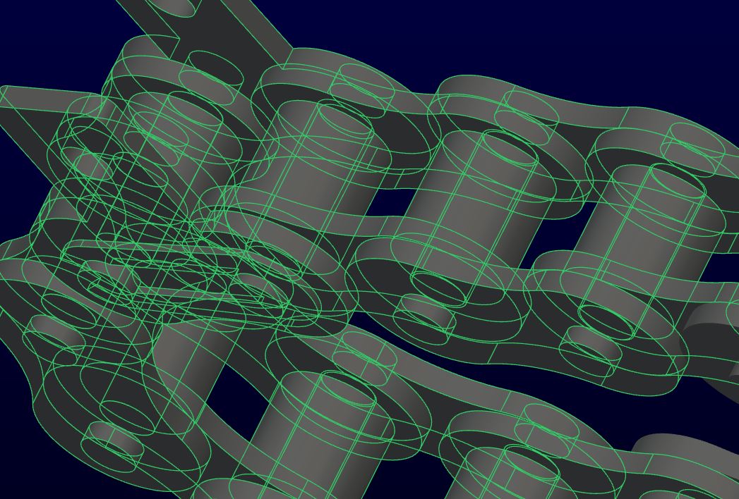
I don't know how much power your computer needs to run this full chain. That's a lot of computation.
However, you can move this chain with the motor I described earlier. You would use rotating motor like my example video, but you would put it on a linear motion motor that would drive between the two ends. It will be an interesting exercise but I would certainly make a simplified model to test the motor aspects before deploying it in this model
May 09, 2013
12:45 PM
- Mark as New
- Bookmark
- Subscribe
- Mute
- Subscribe to RSS Feed
- Permalink
- Notify Moderator
Please log in to access translation
May 09, 2013
12:45 PM
Thanks, I will do that. I did not know about the cylinder vs axis benfits. Right now I'm working with just 5 links with one of them with an attached lever that has a slot-follower.
I'm not sure how I would apply the motor you are talking about. Right now the motor I can apply will only take it in one direction as it requires a vector.
May 09, 2013
01:09 PM
- Mark as New
- Bookmark
- Subscribe
- Mute
- Subscribe to RSS Feed
- Permalink
- Notify Moderator
Please log in to access translation
May 09, 2013
01:09 PM
As I will gladly admit, I am no expert at MDX but I know how to make the system work for me if I give it a good nights rest.
Not knowing if it is directly possible, you could think of making a linear motor this way:
1: define a servo motor and control the -position- with either cosine curve set to 0 - 180 - -180 - 0 (this is hidden part A)
2: define a -generic gear- that is linked the servo motor "part A" as a linear slide (see the infamous meter tutorial). This is the slot servo motor carrier (hidden part part B).
3. Constrain the "slot follower" servo motor to the linear slide "part B". Set the timing of part A and the slot servo motor identical.
To smooth out the motion, you will likely need to create a define the motion graph for the slot follower servo motor. It shouldn't be hard to get a relatively smooth velocity throughout the motion. For instance, use position and hold it in position (0 and 180) while traversing the linear distance.
WARNING: ...and disclaimer; I might be making this a lot harder than it needs to be. I don't know if I can make a linear motor with core Creo (or WF for that matter). I also don't know if you are using the Advanced Mechanism Extension which should have a lot more power, like slot motors. I welcome anyone to set me straight if I am overlooking some basic core functionality and show us how to use it.


