
Turn on suggestions
Auto-suggest helps you quickly narrow down your search results by suggesting possible matches as you type.
Showing results for
Please log in to access translation
Turn on suggestions
Auto-suggest helps you quickly narrow down your search results by suggesting possible matches as you type.
Showing results for
Community Tip - You can Bookmark boards, posts or articles that you'd like to access again easily! X
- Community
- Creo+ and Creo Parametric
- 3D Part & Assembly Design
- Re: Map keys and Parameters WF4 or WF5
Translate the entire conversation x
Please log in to access translation
Options
- Subscribe to RSS Feed
- Mark Topic as New
- Mark Topic as Read
- Float this Topic for Current User
- Bookmark
- Subscribe
- Mute
- Printer Friendly Page
Map keys and Parameters WF4 or WF5
Feb 12, 2014
09:46 AM
- Mark as New
- Bookmark
- Subscribe
- Mute
- Subscribe to RSS Feed
- Permalink
- Notify Moderator
Please log in to access translation
Feb 12, 2014
09:46 AM
Map keys and Parameters WF4 or WF5
I am new to PRO/E so if there is an easier way to go about this please let me know. My problem is that I need to put a special text on my parts. Currently to place the text I have each letter saved as a sketch and on the palette and then I go and place each letter individual as an extrude. Could I make a parameter called part_name that was a string and was seven letters long, and then create a mapkey that would look at part_name and place the appropriate sketch from the palette?
This thread is inactive and closed by the PTC Community Management Team. If you would like to provide a reply and re-open this thread, please notify the moderator and reference the thread. You may also use "Start a topic" button to ask a new question. Please be sure to include what version of the PTC product you are using so another community member knowledgeable about your version may be able to assist.
Labels:
- Labels:
-
General
7 REPLIES 7
Feb 12, 2014
10:00 AM
- Mark as New
- Bookmark
- Subscribe
- Mute
- Subscribe to RSS Feed
- Permalink
- Notify Moderator
Please log in to access translation
Feb 12, 2014
10:00 AM
here is what I do you may be able to adapt it for your needs. I add this realation file_name = rel_model_name
I then create a cosmetic groove and point that to the parameter.
Feb 12, 2014
10:07 AM
- Mark as New
- Bookmark
- Subscribe
- Mute
- Subscribe to RSS Feed
- Permalink
- Notify Moderator
Please log in to access translation
Feb 12, 2014
10:07 AM
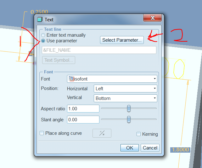
oh that is cool i just started theextrude tool and created text with the text tool and selected the parameter. and now i have some sweet extruded letters 
Feb 12, 2014
10:19 AM
- Mark as New
- Bookmark
- Subscribe
- Mute
- Subscribe to RSS Feed
- Permalink
- Notify Moderator
Please log in to access translation
Feb 12, 2014
10:19 AM
Nick,
I have seen that before and it works great but our machines only read a special font. Would you know how I could load this font into the text tool or the cosmetic groove feature?
Feb 12, 2014
10:25 AM
- Mark as New
- Bookmark
- Subscribe
- Mute
- Subscribe to RSS Feed
- Permalink
- Notify Moderator
Please log in to access translation
Feb 12, 2014
10:25 AM
oh is that all  what format are your letters in now? do you have them in .fnt file? If so you could just add it to this dir C:\PTC\Creo Elements\Pro5.0\x86e_win64\text\usascii restart pro and see if it is added to the list of fonts
Feb 12, 2014
10:56 AM
- Mark as New
- Bookmark
- Subscribe
- Mute
- Subscribe to RSS Feed
- Permalink
- Notify Moderator
Please log in to access translation
Feb 12, 2014
10:56 AM
ok so I just did some reading and my font does not have a .fnt file. The only place this text exist is as sketches in .dwg files. Which I guess brings me back to making a mapkey to place the sketch.
Feb 12, 2014
11:32 AM
- Mark as New
- Bookmark
- Subscribe
- Mute
- Subscribe to RSS Feed
- Permalink
- Notify Moderator
Please log in to access translation
Feb 12, 2014
11:32 AM
If you create your text from the sketcher pallet as a extrude. how are you defining the exttrude as a boss or as a pocket? How then are you programming your machine is it at the control or are you using pro manufacuting?
Feb 12, 2014
01:39 PM
- Mark as New
- Bookmark
- Subscribe
- Mute
- Subscribe to RSS Feed
- Permalink
- Notify Moderator
Please log in to access translation
Feb 12, 2014
01:39 PM
This should work, but it's not as easy as one might hope.
Create a family table User Defined Feature (UDF) for the letters.
Create within the part Program (Tools/Program) a lookup replacement for the UDF family table members based on a string parameter.
You place the UDFs on the part and then the program would Replace each instance based on extracting the matching letter of the parameter.
From the Pro/Program help:
RELATIONS
INST_NAME = LOOKUP_INST ("PEG.PRT", 0, "D2", D6:0, "D1", D5:0 + 1) <- Customize for A-Z, 0-9, et al.
END RELATIONS
Then, at the component ...
ADD PART (INST_NAME)
INTERNAL COMPONENT ID 2
PARENTS = 1 (#1)
END ADD


