
Turn on suggestions
Auto-suggest helps you quickly narrow down your search results by suggesting possible matches as you type.
Showing results for
Please log in to access translation
Turn on suggestions
Auto-suggest helps you quickly narrow down your search results by suggesting possible matches as you type.
Showing results for
Community Tip - Want the oppurtunity to discuss enhancements to PTC products? Join a working group! X
- Community
- Creo+ and Creo Parametric
- 3D Part & Assembly Design
- Re: Mechanism does not work
Translate the entire conversation x
Please log in to access translation
Options
- Subscribe to RSS Feed
- Mark Topic as New
- Mark Topic as Read
- Float this Topic for Current User
- Bookmark
- Subscribe
- Mute
- Printer Friendly Page
Mechanism does not work
Feb 18, 2021
10:45 AM
- Mark as New
- Bookmark
- Subscribe
- Mute
- Subscribe to RSS Feed
- Permalink
- Notify Moderator
Please log in to access translation
Feb 18, 2021
10:45 AM
Mechanism does not work
Hi,
I want to analyze a mechanism but I don't know how to implement it.
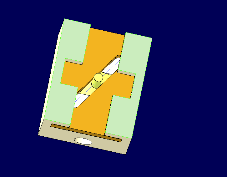
The pictures shows the 3 parts of the assembly.
- Housing
- Lever
- plate with a slot.
The plate with the slot moves back and forth. The pin of the Lever stuck in the slot. This causes the lever to move.
I tried different approaches but none of them worked properly.
Thanks for the help.
Labels:
- Labels:
-
3D Animation
6 REPLIES 6
Feb 18, 2021
10:11 PM
- Mark as New
- Bookmark
- Subscribe
- Mute
- Subscribe to RSS Feed
- Permalink
- Notify Moderator
Please log in to access translation
Feb 18, 2021
10:11 PM
Please at least describe what you tried and why it didn't work properly.
Feb 19, 2021
04:30 AM
- Mark as New
- Bookmark
- Subscribe
- Mute
- Subscribe to RSS Feed
- Permalink
- Notify Moderator
Please log in to access translation
Feb 19, 2021
04:30 AM
ok.
I tried several things.
- Assemby costraints: Slot connection. It did not work because the condition is point to line. In this case, the axis of the lever should follow the slot. The pin is not perpendicular in the right and left position.
- 3D-contacts: I have tried different approaches. It slips through the plate or the plate can no longer be moved properly.
I have unfortunately not found an example to imitate it.
- Tags:
- .
Feb 19, 2021
10:08 AM
- Mark as New
- Bookmark
- Subscribe
- Mute
- Subscribe to RSS Feed
- Permalink
- Notify Moderator
Please log in to access translation
Feb 19, 2021
10:08 AM
I don't like 3D contacts. I much prefer point on line connections like you have here. The problem with this is that the intersection point on the lever needs to move up and down as it's rotated. I would suggest creating a third moving part, with no solid geometry, that can be used to link the two other parts together. It would use a slider connection and be allowed to slide left and right, and always stay at the same vertical position as the orange plate. Create a line through the axis of the yellow lever and then a point in this 'dummy' part. Using a point on line constraint, the dummy part will move left and right as the lever is rotated. Then use this same point in the dummy part to drive the line in the orange part.
Hopefully that makes sense... If not, attach your CAD models and I'll create the extra part and send it back for you to look at.
Feb 22, 2021
04:11 AM
- Mark as New
- Bookmark
- Subscribe
- Mute
- Subscribe to RSS Feed
- Permalink
- Notify Moderator
Please log in to access translation
Feb 22, 2021
04:11 AM
Thank you for the solution!!!
Feb 19, 2021
02:58 PM
- Mark as New
- Bookmark
- Subscribe
- Mute
- Subscribe to RSS Feed
- Permalink
- Notify Moderator
Please log in to access translation
Feb 19, 2021
02:58 PM
Well, I'm not sure how realistic your analysis needs to be, so:
-3D contacts is probably what you want to do if you want more realistic simulation, including "dead zone" However, as you found, it's easy for the 3D contacts to lose their connections. Maybe try changing the mechanism accuracy settings?

Also, maybe rounding the edges of the slot? I find it produces smoother motion (full round works best). If I don't swing that lever around too fast, it stays connected:

Lastly, if you are only looking for roughly descriptive motion, then I think general connection could work here.
For example, I made a point on the lever part and the purple surface on the sliding plate slot part:

Then in the assembly:

(connection made in the lever part. 1st connection is the pin that constraints its rotation within the housing. 2nd connection is the general type, which makes the yellow point be coincident on the purple surface.
Feb 22, 2021
04:09 AM
- Mark as New
- Bookmark
- Subscribe
- Mute
- Subscribe to RSS Feed
- Permalink
- Notify Moderator
Please log in to access translation
Feb 22, 2021
04:09 AM
Thank you for the solution!


