Community Tip - Learn all about PTC Community Badges. Engage with PTC and see how many you can earn! X
- Community
- Creo+ and Creo Parametric
- 3D Part & Assembly Design
- Re: Missing hidden lines in Creo 2.0 drawing
- Subscribe to RSS Feed
- Mark Topic as New
- Mark Topic as Read
- Float this Topic for Current User
- Bookmark
- Subscribe
- Mute
- Printer Friendly Page
Missing hidden lines in Creo 2.0 drawing
- Mark as New
- Bookmark
- Subscribe
- Mute
- Subscribe to RSS Feed
- Permalink
- Notify Moderator
Missing hidden lines in Creo 2.0 drawing
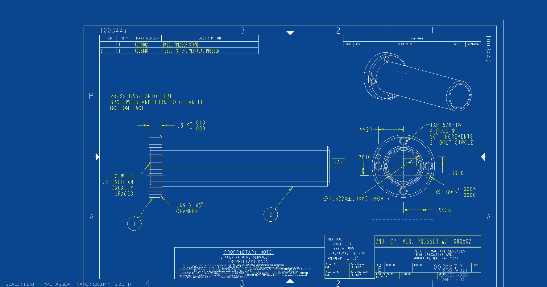
Hello Everyone, I am having an issue with hidden lines in the drawing as it is displayed on the monitor. When I make each view "hidden" the hidden lines are the same color and pattern as the rest of the geometry. however when i print or export to pdf or dwg it does show the hidden dashed lines. I have been searching the forums and trying to tweak the pen table but no luck yet. Any ideas to fix?
Here is my current pen table
! Pen 1 = white entities (object lines)
! Pen 2 = yellow entities (text, dimensions, cross hatching)
! Pen 3 = gray entities (hidden lines)
! Pen 4 = red entities (Highlight - Primary (Dark Red)Selected (Red)Secondary Selected (Orange) All items plot as solid lines:
! Spline surface grid (does not plot in drawings)
! Pen 5 = green entities (sheetmetal)
! Pen 6 = cyan entities (section)
! Pen 7 = dark gray entities (dimmed e.g. tangent edges)
! Pen 8 = blue entities (spline surface grid) [use for drawing perimeter border in format]
pen 1 thickness .035 cm; color 0.0 0.0 0.0
pen 2 thickness .018 cm; color 0.0 0.0 0.0
pen 3 color 0.0 0.0 0.0; pattern .2 .1 cm; thickness .025 cm; half_tone_color
pen 4 thickness .050 cm; color 0.0 0.0 0.0
pen 5 thickness .035 cm; color 0.0 0.0 0.0
pen 6 thickness .018 cm; color 0.0 0.0 0.0
pen 7 thickness .008 cm; color 0.0 0.0 0.0
pen 8 thickness .050 cm; color 0.0 0.0 0.0
Solved! Go to Solution.
- Labels:
-
2D Drawing
Accepted Solutions
- Mark as New
- Bookmark
- Subscribe
- Mute
- Subscribe to RSS Feed
- Permalink
- Notify Moderator
Jon,
I am little bit confused ...
Info no.1:
The color of hidden lines can be set in Creo Parametric Options dialog box.
Click File > Options > System Colors > Graphics and set Hidden Line color.
Info no.2:
I do not know whether it is possible to display hidden lines as dashed lines on the screen.
Martin Hanak
Martin Hanák
- Mark as New
- Bookmark
- Subscribe
- Mute
- Subscribe to RSS Feed
- Permalink
- Notify Moderator
Jon,
to be able to suggest something, I need to have Creo drawing and models. Please upload some example data.
Martin Hanak
Martin Hanák
- Mark as New
- Bookmark
- Subscribe
- Mute
- Subscribe to RSS Feed
- Permalink
- Notify Moderator
Hi Martin,
The attached file shows three views. The ISO is no hidden lines and is fine. The bottom left view is hidden lines turned on but shows the ID of the tube as a slightly different color and solid line. Should be a dashed (hidden) line. 
- Mark as New
- Bookmark
- Subscribe
- Mute
- Subscribe to RSS Feed
- Permalink
- Notify Moderator
Jon,
I am little bit confused ...
Info no.1:
The color of hidden lines can be set in Creo Parametric Options dialog box.
Click File > Options > System Colors > Graphics and set Hidden Line color.
Info no.2:
I do not know whether it is possible to display hidden lines as dashed lines on the screen.
Martin Hanak
Martin Hanák
- Mark as New
- Bookmark
- Subscribe
- Mute
- Subscribe to RSS Feed
- Permalink
- Notify Moderator
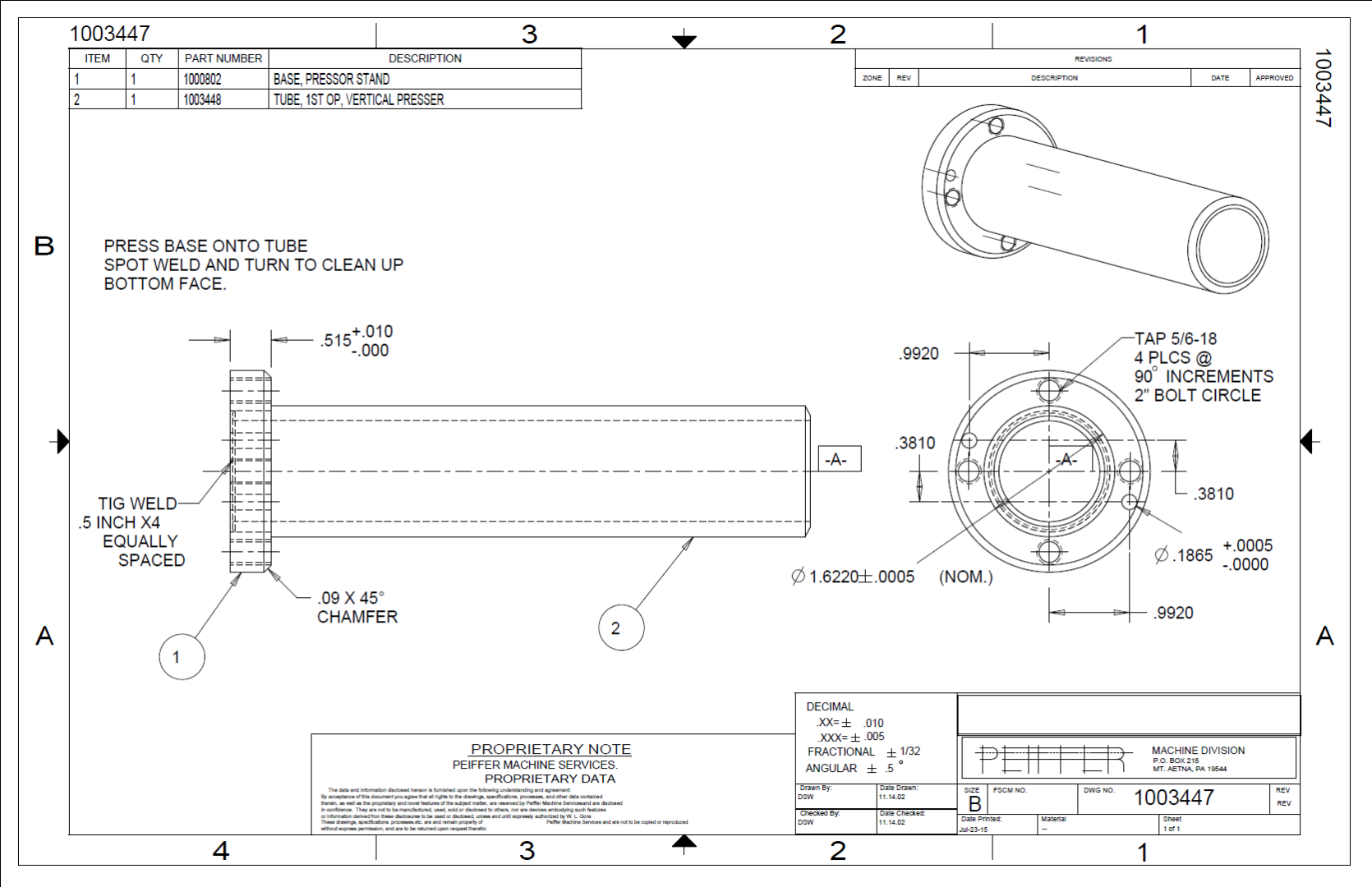
It is possible to display hidden lines as dashed line on the screen. This is how it worked in Creo 1.0. When we upgraded to Creo 2.0 they were gone. This is the output to pdf. Notice how the hidden lines are displayed correctly. This is how it used to look and what i am trying to get it back to.

- Mark as New
- Bookmark
- Subscribe
- Mute
- Subscribe to RSS Feed
- Permalink
- Notify Moderator
I don't recall ever seeing dashed lines on the drawings in Pro/e (or Creo). Always "dimmed" or gray. Output to pdf or printer handled the dashed lines.
Your pen table file is only for printing, not screen display.
- Mark as New
- Bookmark
- Subscribe
- Mute
- Subscribe to RSS Feed
- Permalink
- Notify Moderator
Jon,
I guess that black&white picture is screen capture of PDF file (created from Creo 1.0) displayed on the screen. Is it true ?
What did you get when you create PDF file in Creo 2.0 ?
To get the right PDF, you have to use the following config.pro options:
pdf_use_pentable yes
use_8_plotter_pens yes
Martin Hanak
Martin Hanák
- Mark as New
- Bookmark
- Subscribe
- Mute
- Subscribe to RSS Feed
- Permalink
- Notify Moderator
the black and white picture is a screen cap from the PDF file that was created from Creo 2.0. The PDF works fine as well as printing directly from Creo. The only problem is how hidden lines are displayed on screen. The are displayed as solid lines and it makes it difficult to see the geometry correctly when dimensioning.
- Mark as New
- Bookmark
- Subscribe
- Mute
- Subscribe to RSS Feed
- Permalink
- Notify Moderator
Jon,
I am sorry, I have never seen hidden lines displayed as dashed lines in Drawing mode. To recognize hidden lines in Drawing mode, change their color using my tip entered on 16:20.
Martin Hanak
Martin Hanák
- Mark as New
- Bookmark
- Subscribe
- Mute
- Subscribe to RSS Feed
- Permalink
- Notify Moderator
It is pretty frustrating that Creo does not follow accepted draughting practice i.e. dashed line for hidden.
- Mark as New
- Bookmark
- Subscribe
- Mute
- Subscribe to RSS Feed
- Permalink
- Notify Moderator
We skipped over Creo 1.0 in our program usage, but have used Pro/E since the dawn of time (1990s). The behavior you describe (hidden lines in dark gray or whatever you specify) is how it's always been. It's been that way so long that my mind automatically interprets the dimmed lines as hidden, to the point where I had to confirm that they aren't actually dashed on the screen. It's not a case of seeing what you'll get on the printed (or PDF) output, but that's the way it is.
- Mark as New
- Bookmark
- Subscribe
- Mute
- Subscribe to RSS Feed
- Permalink
- Notify Moderator
What I meant was normal drawing practice (as opposed to PTC practice) is to use dashed lines for hidden detail and this is used for Creo drawing output but I ask why is it not used in modelling mode. It is used in conventional drawing practice to make the hidden detail easy to distinguish from non-hidden detail. I find it really difficult in some models to know what you are looking at, dashed lines would make this so much clearer.
- Mark as New
- Bookmark
- Subscribe
- Mute
- Subscribe to RSS Feed
- Permalink
- Notify Moderator
Color coding of hidden lines allows identification of hidden segments that are too small to adequately represent with dashes. It is also computationally efficient - no need to calculate the separate segments, just change the color if the surface normals of the adjacent surfaces are both into the screen.
You can change the color of hidden lines to make them more obvious as well as changing the background color to enhance the contrast.
For me, once the part complexity reaches a certain point I see no need for the clutter of dashed-line confetti and rarely use a hidden line display when working on solid models any more than I depend on them when handling actual objects.
- Mark as New
- Bookmark
- Subscribe
- Mute
- Subscribe to RSS Feed
- Permalink
- Notify Moderator
Jon,
Hidden line display as dashed line in drawing views was never a part of functionality. Hidden lines will display as light solid lines and will appear as dashed lines on print/pdf.


