
Turn on suggestions
Auto-suggest helps you quickly narrow down your search results by suggesting possible matches as you type.
Showing results for
Please log in to access translation
Turn on suggestions
Auto-suggest helps you quickly narrow down your search results by suggesting possible matches as you type.
Showing results for
Community Tip - When posting, your subject should be specific and summarize your question. Here are some additional tips on asking a great question. X
- Community
- Creo+ and Creo Parametric
- 3D Part & Assembly Design
- Re: Modal Analysis
Translate the entire conversation x
Please log in to access translation
Options
- Subscribe to RSS Feed
- Mark Topic as New
- Mark Topic as Read
- Float this Topic for Current User
- Bookmark
- Subscribe
- Mute
- Printer Friendly Page
Modal Analysis
May 15, 2012
03:56 AM
- Mark as New
- Bookmark
- Subscribe
- Mute
- Subscribe to RSS Feed
- Permalink
- Notify Moderator
Please log in to access translation
May 15, 2012
03:56 AM
Modal Analysis
Hi everyone
Need help regarding modal analysis:
- What is the significance of rigid mode frequency?
- Where I fail in defining the following two models (zipped in part name ex_7-7-1.prt, ex_7-21.prt) exactly as given in problem?
I have already created 2 another models and Creo to solve.
Their solution are quite exact but above 2 problems are not solved accurately.
May be the latter problems have constraints defined and these are unconstrained type.
So how can I fix these models?
Also how will I define the external torque in the model given in problem 7.21?
In the output result window, simulate does not provide any mode shape
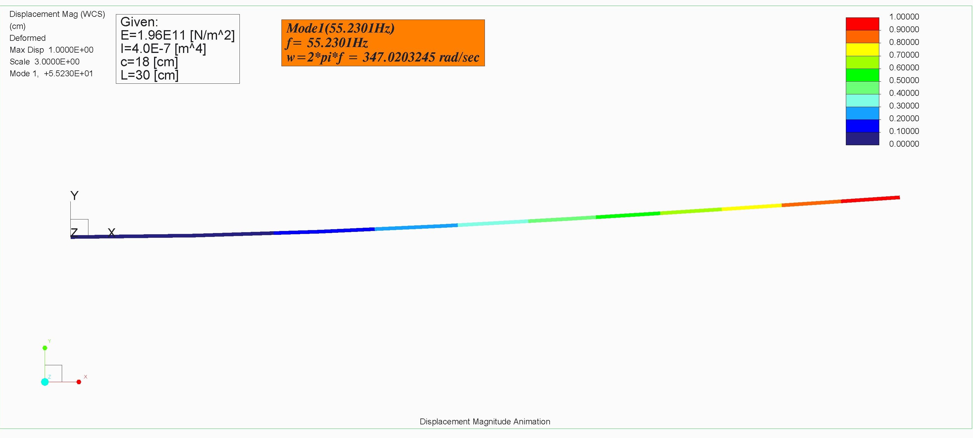
Except one problem which is in planer degree of freedom (Displacement Plot given below)
But in the textbook modes shapes are also asked and they are plotted too in the solution of one of problem.
What type of solution approach is applied by Creo Simulate in solving these multi degree of freedom systems
Is that one of the following?
- Rayleigh Method
- Dunkerley method
- Rayleigh -Ritz Method
- Matrix iteration method
- Holzer method
- Computer oriented Numerical method
Solution:
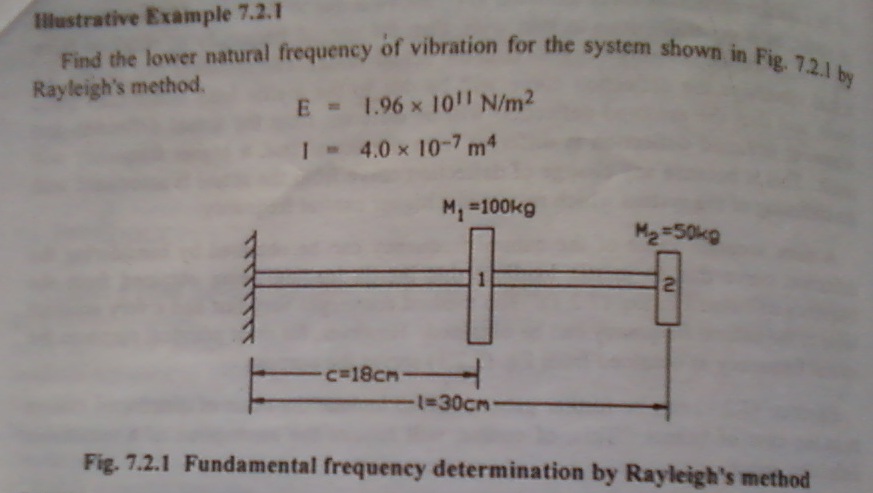
Problem 7.2.1 Natural Frequency (Wn) = 355 rad/sec by Rayleigh Method
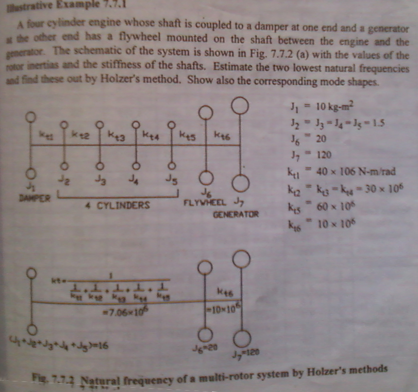
Problem 7.7.1 1st Natural Frequency (Wn1) = 537 rad/sec by Holzer Method
2nd Natural Frequency (Wn2) =1110 rad/sec
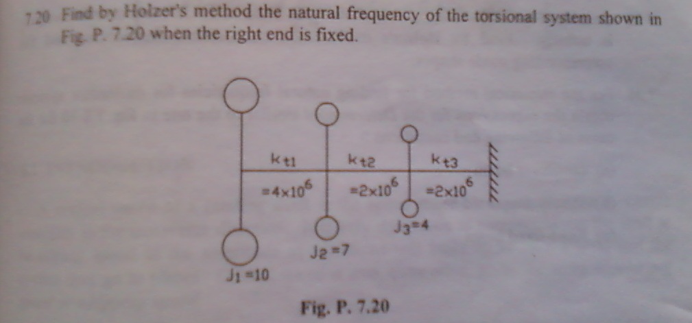
Problem 7.20 Natural Frequency (Wn) =226 rad/sec by Holzer Method
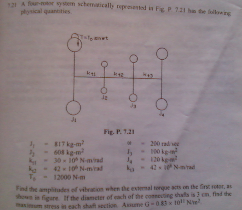
Problem 7.21 B1 = .00008 rad by Holzer Method
This thread is inactive and closed by the PTC Community Management Team. If you would like to provide a reply and re-open this thread, please notify the moderator and reference the thread. You may also use "Start a topic" button to ask a new question. Please be sure to include what version of the PTC product you are using so another community member knowledgeable about your version may be able to assist.
Solved! Go to Solution.
ACCEPTED SOLUTION
Accepted Solutions
May 22, 2012
09:36 AM
- Mark as New
- Bookmark
- Subscribe
- Mute
- Subscribe to RSS Feed
- Permalink
- Notify Moderator
Please log in to access translation
May 22, 2012
09:36 AM
Kulbir,
- Model the spring-rotor system as you have done and then run an unconstrained modal analysis. You should see a number of rigid modes and then the first 3 flexible modes should be at 40.97, 72.11 and 164.90 Hz.
- Now constrain the 2 end points so that they are free to rotate in all 3 degrees but are locked in all 3 translational degrees. Run a constrained modal analysis and you should get the same flexible modes as shown above. You can actually lock 2 more rotational degrees and leave X free, as long as you get the same response from the system. Once you lock to many DOF's, the response will change as you would expect.
You need to make some assumptions about these systems, like that you need at least 2 bearings for this thing to operate. Some problems with multiple rotor/shaft systems state this, while others do not. Some shown bearings in the actual diagram or fixed constraints like your cantilever shaft.
I think you could also find out where the nodes are and constrain those in the proper manner to get the same response. This would require hand calcs and then setting the Mechanica model differently, but should work.
Modeling systems like these to find natural frequencies is pretty easy to do, as you have shown. It is a great way to double check Holzer's method using a spreadsheet or using MathCAD. Once you get past the natural frequency though, you need to be careful in using Mechanica and how you setup the model. I'm no expert at all on the dynamic analyses, so take this with a grain of salt.
Can you share your calculations of the amplitude of vibration for this problem?
4 REPLIES 4
May 16, 2012
07:56 AM
- Mark as New
- Bookmark
- Subscribe
- Mute
- Subscribe to RSS Feed
- Permalink
- Notify Moderator
Please log in to access translation
May 16, 2012
07:56 AM
Kulbir,
- Rigid body modes exist in a body when there is not enough support (constraints) to keep the body from moving as a whole. A single body with no constraints will have 3 rotational and 3 translational DOF. If you performed a modal analysis on a body with no constraints you would want to know what these rigid modes were and Mechanica gives you that option, like most other packages. Your rigid modes will be at or very near a zero. Your text book should cover this and there is a ton of information on the web that explains and shows this in detail.
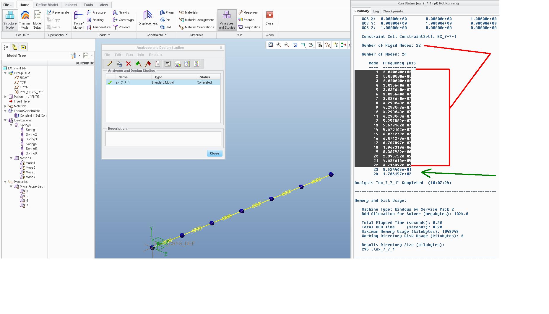
- For problem 7.7.1, you have incorrect J values for MASS 2. It should be J2 but it is showing as J7. Once that is fixed you can run the analysis like you had setup, UNCONSTRAINED with RIGID MODE SEARCH and MAX FREQUENCY of 200 Hz. You should find that the first 22 modes are rigid modes. I have attached a screen shot of this and the values of the 23rd and 24th mode appear to be correct. You should try playing around with this one and adding constraints and then run a constrained analysis to see what happens to your rigid modes.
- For problem 7.2.1, don't worry too much about the slight difference in your values compared to the book answer. The idea of using Rayleigh or Holzer's method first and then checking it with an FEA model is great and you seem to have found that the first natural frequency is around 350 rad/sec. I tried this with a quick model and used Pro/E material of STEEL and a beam with radius of 2.67 cm and found a value of 350.1 rad/sec.
For the mode shapes you already have this done and shown in your picture and could animate it if you needed.The idea is that that the mode shape plotted here shows relative displacement at certain points along your beam, plotted on a 0 to 1 scale. So looking at your picture, the middle of the beam will have a displacement 0.3 times that of the far end of the beam at 1. The actual displacement values can't be determined until a dynamic analysis is run and some type of forcing function is applied to this system. Go back and run the analysis again and this time look for the first 2 modes, then plot them side by side, this might help you out.
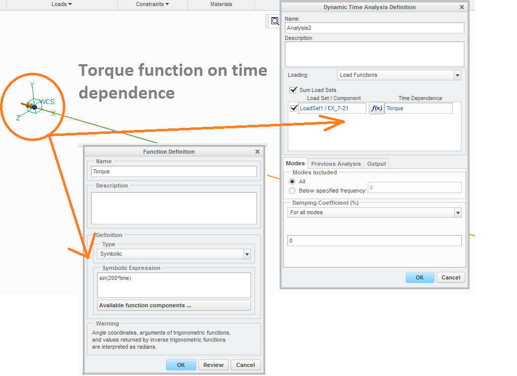
- For problem 7.21, you need to run the modal analysis and then a dynamic time analysis. You should be able to add the torque to the model and then under the analysis setup option you define the torque as a time dependence function with the equation given. You also need to make sure define the appropriate measures for stresses and displacements. Without measures the dynamic analyses are worhtless. There is good information in the help section on how to setup and run these.
Hope this helps,
May 18, 2012
08:39 AM
- Mark as New
- Bookmark
- Subscribe
- Mute
- Subscribe to RSS Feed
- Permalink
- Notify Moderator
Please log in to access translation
May 18, 2012
08:39 AM
Sir, Thanks for a lot of information
Actually I had added two problems to sort out and two solved problems(problem 7.2.1 and 7.20) as they are linked to my question statement and previous problems.
One is solved when you dictate my mistake in problem 7.7.1
Other remained unsolved, when I define torque as time dependence in the Dynamic Time analysis for problem 7.21 without adding constraints in constraint set,

it shows the constraint error.
Because the constraint are the primary requirement to run the dynamic time analysis.
How to constraint the model in order not to effect the given problem scenario.
State other assumptions if required.
May 22, 2012
09:36 AM
- Mark as New
- Bookmark
- Subscribe
- Mute
- Subscribe to RSS Feed
- Permalink
- Notify Moderator
Please log in to access translation
May 22, 2012
09:36 AM
Kulbir,
- Model the spring-rotor system as you have done and then run an unconstrained modal analysis. You should see a number of rigid modes and then the first 3 flexible modes should be at 40.97, 72.11 and 164.90 Hz.
- Now constrain the 2 end points so that they are free to rotate in all 3 degrees but are locked in all 3 translational degrees. Run a constrained modal analysis and you should get the same flexible modes as shown above. You can actually lock 2 more rotational degrees and leave X free, as long as you get the same response from the system. Once you lock to many DOF's, the response will change as you would expect.
You need to make some assumptions about these systems, like that you need at least 2 bearings for this thing to operate. Some problems with multiple rotor/shaft systems state this, while others do not. Some shown bearings in the actual diagram or fixed constraints like your cantilever shaft.
I think you could also find out where the nodes are and constrain those in the proper manner to get the same response. This would require hand calcs and then setting the Mechanica model differently, but should work.
Modeling systems like these to find natural frequencies is pretty easy to do, as you have shown. It is a great way to double check Holzer's method using a spreadsheet or using MathCAD. Once you get past the natural frequency though, you need to be careful in using Mechanica and how you setup the model. I'm no expert at all on the dynamic analyses, so take this with a grain of salt.
Can you share your calculations of the amplitude of vibration for this problem?
Jul 11, 2012
08:34 PM
- Mark as New
- Bookmark
- Subscribe
- Mute
- Subscribe to RSS Feed
- Permalink
- Notify Moderator
Please log in to access translation
Jul 11, 2012
08:34 PM
Sorry for late response, I could not reply. Exams were there. Goes well and nice to meet you again, Sir.
I have done some work on my notebook and here are the scanned images in my best way to explain the theoretical solution. Hopefully I am justified with that some problem may need to be solved by hand calculations.
One more thing I don’t know how to use computational measure in Creo Simulate. In all above problems, Wn = 2*pi*frequency. And frequency is the global measure of modal analysis - modal_frequency. But this don’t work. And there is no example of any computational measure in help context.
So I want to know what are the variables which can be used in computational measure definition area.
Regards


