Community Tip - Did you know you can set a signature that will be added to all your posts? Set it here! X
- Community
- Creo+ and Creo Parametric
- 3D Part & Assembly Design
- Re: Modelling advice - cylindrical pv nozzle
- Subscribe to RSS Feed
- Mark Topic as New
- Mark Topic as Read
- Float this Topic for Current User
- Bookmark
- Subscribe
- Mute
- Printer Friendly Page
Modelling advice - cylindrical pv nozzle
- Mark as New
- Bookmark
- Subscribe
- Mute
- Subscribe to RSS Feed
- Permalink
- Notify Moderator
Modelling advice - cylindrical pv nozzle
Hello,
Just wondering if anyone had any advice as to how to go about modelling the cylindrical pressure vessel with nozzle shown below. It is changing in all 3 dimensions, so some kind of mixture of revolve and sweep seems logical. It is for a project so I will figure it out, just wondering if anyone has any helpful advice to save me getting lost.
Thanks
- Labels:
-
General
- Mark as New
- Bookmark
- Subscribe
- Mute
- Subscribe to RSS Feed
- Permalink
- Notify Moderator
Hello, I have made progress but have encountered some issues (which I think are related to the 'blended sweep' function in Creo 2.0).
I have several screenshots here: Pressure_Vessel_Nozzle by rhamill95 | Photobucket [Photobucket link]. The picture titles give some detail as to what they are.
So far I have successfully created what I am fairly confident are the correct section geometries (was given details of these). I then inserted both sketches into one part file and created a 90 deg sketch (quarter circle) to be swept around. I have then used a 'swept blend' of surface one (with the curved wall) to the other around the line. I have also tried using the rotational blend feature which as expected gives the same result.
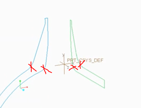
The problem I am having is that wall thickness is not uniform when it is swept. Therefore the pressure vessel would not have a constant wall thickness (as shown below) and I cannot extrude the main cylindrical body through. How can I get fix this issue and produce the geometry as shown in the original question? I have tried playing with the 'tangency' options as shown in the pictures in the link. Thanks for your help and I would really appreciate any replies!
- Mark as New
- Bookmark
- Subscribe
- Mute
- Subscribe to RSS Feed
- Permalink
- Notify Moderator
Your first picture looks like a half cylinder with a nozzle bonded into it.
The second post shows two sections both of which show the nozzle 'thickness' to be quite different than the main 'pressure vessel' geometry.
For constant thickness walls, I would recommend you use the offset or the shell tools. Perhaps break up the problem into modeling the overall vessel and the nozzle somewhat separately.
- Mark as New
- Bookmark
- Subscribe
- Mute
- Subscribe to RSS Feed
- Permalink
- Notify Moderator
Thanks for the response!
The nozzle is incorporated into the cylinder. (I.e. the nozzle wall is thicker in parts however it then runs down into the cylinder so that it merges into the cylinder). The picture included at the end of my second post shows that it is almost right but if zoomed in on, the cylinder wall does not match the nozzle wall as it should. I hope that makes sense as it is difficult to explain!
- Mark as New
- Bookmark
- Subscribe
- Mute
- Subscribe to RSS Feed
- Permalink
- Notify Moderator
If you could post the model we could take a look into it!
Try to see if my model (Creo 3) is suitable for you.
- Mark as New
- Bookmark
- Subscribe
- Mute
- Subscribe to RSS Feed
- Permalink
- Notify Moderator
Blending tangencies like this is no easy task.
The only way I've been able to do this is to use a VSSweep and manage the tangency within the sketch and equations (or graph).
Better yet (below), with curve driven rounds, you could do the merge generically and manage the blending with specialized rounds.
How is this part going to be fabricated?

- Mark as New
- Bookmark
- Subscribe
- Mute
- Subscribe to RSS Feed
- Permalink
- Notify Moderator
Thanks very much for your response! Yes, it took me quite a few days just playing with the model to realise the complexity involved! You seem to be talking about exactly what I require and was unable to figure out how to "manage the tangency" properly. Curve driven rounds also seems like a great solution and your picture seems to have the problem solved exactly like what I am aiming for! Can I ask you to explain how you achieved this? I am trying to learn the method rather than just use an uploaded model etc! I would really appreciate your help! Thanks, Robert
- Mark as New
- Bookmark
- Subscribe
- Mute
- Subscribe to RSS Feed
- Permalink
- Notify Moderator
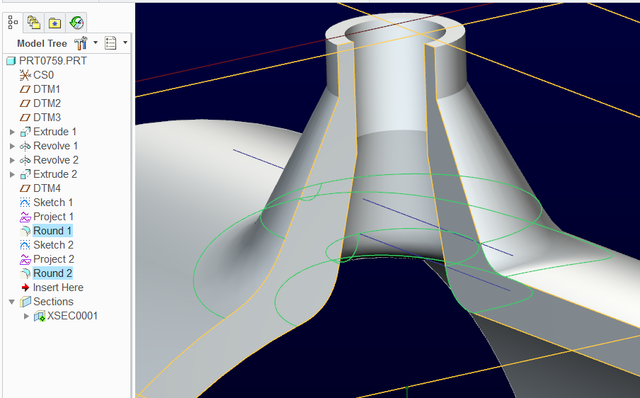
The first part of the tree is simply getting the base geometry:
half pipe
nozzle feature
trim half pipe
trim nozzle feature
...then each round is treated individually (DTM4 is not required)
line for projection onto nozzle feature outside
project the line sketch onto the nozzle outer surface
Round using curve as a guide
Line for projection onto nozzle feature inside
project the line sketch onto the nozzle inner surface
round using curve as a guide
- Mark as New
- Bookmark
- Subscribe
- Mute
- Subscribe to RSS Feed
- Permalink
- Notify Moderator
Thank you very much for your help and sorry for the slow response. I am still not quite able to follow your instructions? E.g. Are the trims cutting the cylinder (nozzle) using the surface of the half cylinder? What line is projected etc? If you are able to provide more details or pics that would be great! if it is easier you can PM me or whatever. I would then be willing to post thoroughly detailed instructions on this post (giving you the credit) in order than others can learn from it as well if people wanted that? Thanks, Robert
- Mark as New
- Bookmark
- Subscribe
- Mute
- Subscribe to RSS Feed
- Permalink
- Notify Moderator
I was being intentionally vague in order for you to study the problem.
You actually did study it and your conclusion for the trim is correct.
Use the half-pipe edge to create a trim extrude of the nozzle.
Use the remaining geometry of the nozzle to create a revolve cut to trim away the half-pipe clogging the hole.
The Project is a simple line sketch that is projected onto surfaces. This one is on the help files.
You see the two blue lines in my image above. These are the trace lines for the rounds.
You only constrain one end of the round using this method.
- Mark as New
- Bookmark
- Subscribe
- Mute
- Subscribe to RSS Feed
- Permalink
- Notify Moderator
Hello,
Sorry for the delay, I have been extremely busy lately and it took me a while to figure it all out and finally recorded a video this morning. As you can see in the video I managed to get the correct shape of geometry but am not able to figure out how to get the geometry to match the given dimensions. As shown in the video the initial 2 sketches are the correct geometry but when adding the rounds I am only able to match it up to one geometry or the other. For my project work this geometry is close enough but for future reference (and out of personal curiosity) - does anyone know how I could fix this?
Thanks,
Robert
- Mark as New
- Bookmark
- Subscribe
- Mute
- Subscribe to RSS Feed
- Permalink
- Notify Moderator
Try taking out these sketch rounds. Leave them in a spare sketch just to confirm your geometry against a cross section view.
You might need to make up for the fact that one the radius-edge is not linear. Now you have to plot that curve to match it exactly.
This could be an equation curve.
I understand the difficulty this could present when you have to match geometry exactly. However, if this is the case, there is typically a theory behind that criticality.
Converting that theory to Creo geometry is always possible. The level of effort could be significant by no fault of PTC. It is simply a difficult tech to convert to CAD.

- Mark as New
- Bookmark
- Subscribe
- Mute
- Subscribe to RSS Feed
- Permalink
- Notify Moderator
It's not my field of modeling. Anyway i made a quilt and then thickened (3mm). After this only one point wasn't 3 mm (thickness analysis). Someone expert of this can give a check.
- Mark as New
- Bookmark
- Subscribe
- Mute
- Subscribe to RSS Feed
- Permalink
- Notify Moderator
Thanks for your response! I had considered that initially however the model is not actually of uniform thickness (the nozzel thickness varies)! I am not sure if I have permission to upload my model but will find out and see. I am aiming for something like Antonius Dirriwachter has posted, so am hoping he can try to explain how he managed to achieve it and hopefully others can learn from this! Thanks, Robert


