
Turn on suggestions
Auto-suggest helps you quickly narrow down your search results by suggesting possible matches as you type.
Showing results for
Please log in to access translation
Turn on suggestions
Auto-suggest helps you quickly narrow down your search results by suggesting possible matches as you type.
Showing results for
Community Tip - Learn all about PTC Community Badges. Engage with PTC and see how many you can earn! X
- Community
- Creo+ and Creo Parametric
- 3D Part & Assembly Design
- Re: Nautilus Gears
Translate the entire conversation x
Please log in to access translation
Options
- Subscribe to RSS Feed
- Mark Topic as New
- Mark Topic as Read
- Float this Topic for Current User
- Bookmark
- Subscribe
- Mute
- Printer Friendly Page
Nautilus Gears
Mar 14, 2013
10:09 PM
- Mark as New
- Bookmark
- Subscribe
- Mute
- Subscribe to RSS Feed
- Permalink
- Notify Moderator
Please log in to access translation
Mar 14, 2013
10:09 PM
Nautilus Gears
Hello, I am new to Creo and modeling online am trying to make something for fun ( I have found this teaches me much more useful things then the class tutorials.) I am working on making a nautilaus Gear, which can be seen here: http://2.bp.blogspot.com/-0sTpWXq1llY/UBG9BFHXcxI/AAAAAAAAFWI/qio1WPDbnq0/s1600/DSC04545+%2528Custom%2529.JPG
I can make the logarithmec spiral and am able to sweep around it, but I am having some issues making the teeth for the gear. I have tried making one tooh and using th epattern tool to make it, but the teeth are never on the surface. I have tried dozens of times at this point and several different methods to make the teeth. If anyone with more experience has a method for creating these types of spirals I am all ears. Here is the basic shape of spiral with the type of tooth I am looking for.
The tooth isn't exactly to the dimensions I will be doing in the end, but I am working to get the process down before making the final part. The extra bulk in the center is for the future whne I actually have to make a hole for it to revolve around. No date that it is needed by, but I will probably be doing it tomorrow and sometime next week as my spring break just started.
Thanks in advance everyone.
Jamie
This thread is inactive and closed by the PTC Community Management Team. If you would like to provide a reply and re-open this thread, please notify the moderator and reference the thread. You may also use "Start a topic" button to ask a new question. Please be sure to include what version of the PTC product you are using so another community member knowledgeable about your version may be able to assist.
Labels:
- Labels:
-
General
7 REPLIES 7
Mar 14, 2013
10:27 PM
- Mark as New
- Bookmark
- Subscribe
- Mute
- Subscribe to RSS Feed
- Permalink
- Notify Moderator
Please log in to access translation
Mar 14, 2013
10:27 PM
I haven't looked at your file yet. I will give you tip that you need to specify and "alternate origin" for your pattern along curves. Otherwise, the pattern seems to use a "bounding box" to determine the pattern origin. This should get you past the critical issue with defining the distribution of "teeth".
Mar 15, 2013
08:46 AM
- Mark as New
- Bookmark
- Subscribe
- Mute
- Subscribe to RSS Feed
- Permalink
- Notify Moderator
Please log in to access translation
Mar 15, 2013
08:46 AM
I thought I would spend a couple of minutes looking at this. It seemed a nice way to spend a little bit of Friday morning.
Most of Friday morning has now gone!
I made a datum curve of the right shape and placed a datum point on the curve. I then made a tooth-shaped protrusion on the curve, referenced to the point, so that the tooth attitude would follow the shape of the curve, instead of staying horizontal or vertical.
Then I patterned the datum point and reference-patterned the protrusion.
Strange behaviour then ensued!
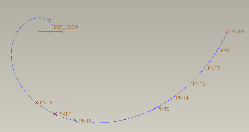
I am at a loss to explain why the pattern of points, equispaced at 0.06 of the curve length pitch, should leap across to some apparently random point on the other side of the curve and proceed in the opposite direction after the first 5 points.
The number 5 seems to be magic - it always either reverses as shown or fails regeneration after 5 points.
Is this what you meant by the 'bounding-box', Antonius? I confess, I didn't understand what you meant before trying it out. I still don't, for that matter... 
Any ideas?
WF2, M220
Have a great weekend, and i will expect the correct answer to be waiting for me on monday morning!
Regards,
John
Mar 15, 2013
03:32 PM
- Mark as New
- Bookmark
- Subscribe
- Mute
- Subscribe to RSS Feed
- Permalink
- Notify Moderator
Please log in to access translation
Mar 15, 2013
03:32 PM
By Bonding Box I mean that patterns create a 3D box around the patterned feature to determine the "origin" of the feature. This is rarely a usable location and creates real problems when following curves or sketches.
The problem you are seeing is not uncommon. I have no explanation for it and I see it all too often. It really should be reported to CS and driven to an SPR. I don't know if this is a Creo thing or if this has always been a problem but since you see it in WF2, it must be inherent to the code. In the recent Wave Washer models, I had this happened when following a surface too.
Mar 15, 2013
06:33 PM
- Mark as New
- Bookmark
- Subscribe
- Mute
- Subscribe to RSS Feed
- Permalink
- Notify Moderator
Please log in to access translation
Mar 15, 2013
06:33 PM
My version of creo can't ope the part. Do you have the cartesian equation for the nautilus you want? Interesting wooden model in the pic......
Mar 18, 2013
07:06 PM
- Mark as New
- Bookmark
- Subscribe
- Mute
- Subscribe to RSS Feed
- Permalink
- Notify Moderator
Please log in to access translation
Mar 18, 2013
07:06 PM
The equation I wsa using I can not access at the moment. I am not in the creo lab. But, try using an equation for cartesian coordinates:
R = t
x = 4 *Cos(180*pi*t)
y = 4 *Sin(180*pi*t)
Thanks for the help and ideas everyone.
Mar 18, 2013
07:02 PM
- Mark as New
- Bookmark
- Subscribe
- Mute
- Subscribe to RSS Feed
- Permalink
- Notify Moderator
Please log in to access translation
Mar 18, 2013
07:02 PM
Still working on this.
I tried your suggestions and have not successfully made any spiral shaped gear. I Tried altering my Log equation and made a simpler Archimides equation, so there was a constant pitch to the curve. This did not help, even with establishing a curve to follow or a point to revolve around. Using the spline tool to follow the curve, or establishing a center point have not created it successfully.
Another method, was I made a single tooth with no bounding curve. I then patterned the tooth around a curve, and based on the way the tooth became patterned, I tried altering the tooth to fill in the blanks created by the pattern. I would have been shocked if this actually, worked for obvious reasons...
At this point I am thinking I am going to have to draw the teeth in manually.
Time will tell,
Thanks for the help everyone,
Jamie
Mar 18, 2013
08:54 PM
- Mark as New
- Bookmark
- Subscribe
- Mute
- Subscribe to RSS Feed
- Permalink
- Notify Moderator
Please log in to access translation
Mar 18, 2013
08:54 PM
You have a student edition which full versions cannot open.
I have created the curve and used it to project into a sketch.
I placed a point on the original curve at the sketch's start point. So far, it is properly distributing the points.
I am using Kevin's equation from HERE
r = 1
ang = (360*1) * t
s = 2 * pi * r * t
x0 = s * cos (ang)
y0 = s * sin (ang)
x = x0 + s * sin (ang)
y = y0-s * cos (ang)


