Community Tip - Want the oppurtunity to discuss enhancements to PTC products? Join a working group! X
- Community
- Creo+ and Creo Parametric
- 3D Part & Assembly Design
- Re: Noobish question: datum plane tanget to chamfe...
- Subscribe to RSS Feed
- Mark Topic as New
- Mark Topic as Read
- Float this Topic for Current User
- Bookmark
- Subscribe
- Mute
- Printer Friendly Page
Noobish question: datum plane tanget to chamfer
- Mark as New
- Bookmark
- Subscribe
- Mute
- Subscribe to RSS Feed
- Permalink
- Notify Moderator
Noobish question: datum plane tanget to chamfer
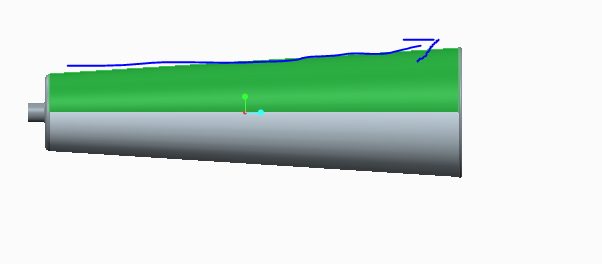
My goal is very simple, and that is to extrude along the surface of this chamfer either by creating a datum plane that goes through it or otherwise. I'm having trouble getting the datum plane to be both parallel to the front AND through the chamfer. The minute I click the first reference to be the chamfer, the option to add the front plane to the reference set disappears.
This is a picture of the situation. To clarify: the arrow is where I want to extrude my elipses so as to create a handle grip, the direction of the extruded ellipses is parallel to the arrow (not normal as you might think i.e. not going out or into the screen). Can anyone help me?

This thread is inactive and closed by the PTC Community Management Team. If you would like to provide a reply and re-open this thread, please notify the moderator and reference the thread. You may also use "Start a topic" button to ask a new question. Please be sure to include what version of the PTC product you are using so another community member knowledgeable about your version may be able to assist.
- Labels:
-
General
- Mark as New
- Bookmark
- Subscribe
- Mute
- Subscribe to RSS Feed
- Permalink
- Notify Moderator
Have you tried holding down control and clicking both references that you want? Your image is not showing up, by the way. Perhaps upload here if you didn't?
- Mark as New
- Bookmark
- Subscribe
- Mute
- Subscribe to RSS Feed
- Permalink
- Notify Moderator

I tried that but like I said. The minute I set the first reference through or tangent to the chamfer, the option for the front plane goes away. Re-upped the image in order to clarify...
- Mark as New
- Bookmark
- Subscribe
- Mute
- Subscribe to RSS Feed
- Permalink
- Notify Moderator
Maybe if you uploaded the part and sketched where you want the plane to be?
- Mark as New
- Bookmark
- Subscribe
- Mute
- Subscribe to RSS Feed
- Permalink
- Notify Moderator
Unless I'm misunderstanding what you want to do or what your model is you can't make a plane tangent to the surface you're showing and parallel to the front. You should be able to make it perpendicular though.
- Mark as New
- Bookmark
- Subscribe
- Mute
- Subscribe to RSS Feed
- Permalink
- Notify Moderator
Abdullah,
1. Where is the chamfer in your picture?
2. You said,
I'm having trouble getting the datum plane to be both parallel to the front AND through the chamfer
Where is the "front" that you fefer to?
-Kevin
- Mark as New
- Bookmark
- Subscribe
- Mute
- Subscribe to RSS Feed
- Permalink
- Notify Moderator
The chamfer is the sloping bit, it extends from the first edge to the second. I uploaded the part as someone has suggested.
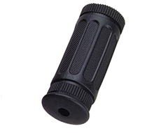
I'm sorry if I'm not explaining this too well. What I want to add is handle grips similar to the ones on this:

How can I do that while still keeping the chamfer?
- Mark as New
- Bookmark
- Subscribe
- Mute
- Subscribe to RSS Feed
- Permalink
- Notify Moderator
One way to do create the recessed geometry is to create a copy of the tapered surface, flatten the quilt, create a sketch of the recess geometry with a sketched coordinate system in the sketch, wrap it around the tapered surface to get the outer surface curve, offset the tapered surface and project (depending onhow you want the base defined) the wrapped curve onto the offset surface, trim the offset surface with the projected curve, create a boundary blend between the two curves, merge the surfaces, copy the merged surface so it can be patterned, and solidify using the remove material option. For the raised ones you can create the surfaces in a similar way. I can post pictures but can't update the model since I'm not using Creo 1.


