
Turn on suggestions
Auto-suggest helps you quickly narrow down your search results by suggesting possible matches as you type.
Showing results for
Please log in to access translation
Turn on suggestions
Auto-suggest helps you quickly narrow down your search results by suggesting possible matches as you type.
Showing results for
- Community
- Creo+ and Creo Parametric
- 3D Part & Assembly Design
- Re: PLOT BORDER
Translate the entire conversation x
Please log in to access translation
Options
- Subscribe to RSS Feed
- Mark Topic as New
- Mark Topic as Read
- Float this Topic for Current User
- Bookmark
- Subscribe
- Mute
- Printer Friendly Page
PLOT BORDER
Jun 21, 2012
11:26 AM
- Mark as New
- Bookmark
- Subscribe
- Mute
- Subscribe to RSS Feed
- Permalink
- Notify Moderator
Please log in to access translation
Jun 21, 2012
11:26 AM
PLOT BORDER
How do I disable plotting of the page outline? My drawing template already has a full border so I don't want to print the automatic border. Config setting? Which one?
This thread is inactive and closed by the PTC Community Management Team. If you would like to provide a reply and re-open this thread, please notify the moderator and reference the thread. You may also use "Start a topic" button to ask a new question. Please be sure to include what version of the PTC product you are using so another community member knowledgeable about your version may be able to assist.
Labels:
- Labels:
-
2D Drawing
13 REPLIES 13
Jun 21, 2012
12:44 PM
- Mark as New
- Bookmark
- Subscribe
- Mute
- Subscribe to RSS Feed
- Permalink
- Notify Moderator
Please log in to access translation
Jun 21, 2012
12:44 PM
this is Creo 1.0 by the way
Jun 21, 2012
04:41 PM
- Mark as New
- Bookmark
- Subscribe
- Mute
- Subscribe to RSS Feed
- Permalink
- Notify Moderator
Please log in to access translation
Jun 21, 2012
04:41 PM
Hi Chris...
I know you can enable/disable the plotting of the format easily enough. However, I'm not so sure about that thin black border that prints with all pages. I've looked through the PCF file documentation and other sources but I don't see anything about disabling that border.
I've tried everything I know how to do... and at least part of it persists. Sometimes I can use the Clipped printer setting to remove some of the lines but not all. Would an option be to remove the outer line from your format border? I know this isn't a solution per se... but it may solve the problem.
In the big picture, I realize this is small potatoes but it should still be possible. Here's a link to the PDF documentation on ptc.com (LINK). I don't see any method of disabling the border. Maybe someone else can chime in?
Thanks!
-Brian
Jun 22, 2012
02:12 AM
- Mark as New
- Bookmark
- Subscribe
- Mute
- Subscribe to RSS Feed
- Permalink
- Notify Moderator
Please log in to access translation
Jun 22, 2012
02:12 AM
Chris,
create your drawing format in Format mode. In this mode you can remove 4 default border lines and define what you want.
Martin Hanak
Martin Hanák
Jun 22, 2012
02:26 AM
- Mark as New
- Bookmark
- Subscribe
- Mute
- Subscribe to RSS Feed
- Permalink
- Notify Moderator
Please log in to access translation
Jun 22, 2012
02:26 AM
Hi Martin...
But zoom in to a portion of your drawing and print... even zoomed in, you get these thin border lines on your final output. These lines are obviously not there in the format because you're zoomed in to a single view or a single portion of the drawing. Yet the lines persist.
He already has format lines at the outer extents of his drawing and he'd like to keep them. But he'd like to remove these "phantom" borders that seem to come from nowhere. I can't seem to find any way to turn them off. Do you have any ideas?
Thanks!
-Brian
Jun 22, 2012
05:05 AM
- Mark as New
- Bookmark
- Subscribe
- Mute
- Subscribe to RSS Feed
- Permalink
- Notify Moderator
Please log in to access translation
Jun 22, 2012
05:05 AM
Brian,
I cannot reproduce the problem.
I created a simple part (a cube). I created empty A3 drawing and put one 3D view into it. I zoomed the view and printed it into PDF and on paper. There is no border in ouput.
Martin Hanak
Martin Hanák
Jun 22, 2012
12:01 PM
- Mark as New
- Bookmark
- Subscribe
- Mute
- Subscribe to RSS Feed
- Permalink
- Notify Moderator
Please log in to access translation
Jun 22, 2012
12:01 PM
Martin...
Are you printing to a PDF directly through Creo, using a Printer from MS Printer Manager, or do you have a printer set up using a custom PCF file?
So far everything I have tried is using MS Printer Manager and using that as the launch point. When the MS Printer Manager window pops, I select one of the printers (or Adobe PDF) and print from there. It always leaves at least a few of the border lines. Maybe the issue is with MS Print Manager... maybe it goes away with a custom printer config file or the internal PDF maker?
Thanks!
-Brian
Jun 25, 2012
05:27 AM
- Mark as New
- Bookmark
- Subscribe
- Mute
- Subscribe to RSS Feed
- Permalink
- Notify Moderator
Please log in to access translation
Jun 25, 2012
05:27 AM
Brian,
my SW configuration is:
- Creo Parametric 1.0 M040
- PDF Creator 1.0.2
I generated PDF through MS Printer Manager printer configuration using PDF Creator 1.0.2.
See uploaded files.
Martin Hanak
Martin Hanák
Jun 25, 2012
12:57 PM
- Mark as New
- Bookmark
- Subscribe
- Mute
- Subscribe to RSS Feed
- Permalink
- Notify Moderator
Please log in to access translation
Jun 25, 2012
12:57 PM
Yep... you're right. No border on your image!
If I print that same model on either Adobe PDF printer (through MS Printer Manager) or CutePDF (a freeware PDF creator), I get a partial border. Here's the two resulting images (attached).
As a side note, after a good deal of fiddling, I was able to get ONE image without a border. However, when attempting to reproduce the same results (no border), I was NOT able to duplicate them! I got one image to print without a border exactly once but couldn't get it to repeat!
I'm not sure what's going on... any ideas?
Thanks!
-Brian
Jun 26, 2012
03:20 AM
- Mark as New
- Bookmark
- Subscribe
- Mute
- Subscribe to RSS Feed
- Permalink
- Notify Moderator
Please log in to access translation
Jun 26, 2012
03:20 AM
Brian,
the explanation is very easy  .
.
My drawing (x1.drw) contains 4 default border lines. When you print the drawing displayed in default size (i.e. after applying Refit command) and open resulting PDF file, you will see the top and right line belonging to the default drawing border.
You can turn off border lines by following setting:
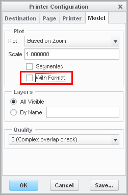
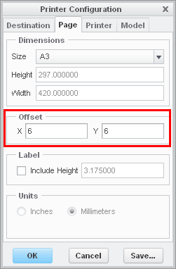
You can move border lines to align them with paper edges by following setting:
If you zoom out the drawing, you will see the whole drawing border in PDF file.
If you zoom in the drawing, drawing border will go out of the "paper".
Martin Hanak
Martin Hanák
Jun 26, 2012
02:45 PM
- Mark as New
- Bookmark
- Subscribe
- Mute
- Subscribe to RSS Feed
- Permalink
- Notify Moderator
Please log in to access translation
Jun 26, 2012
02:45 PM
Hi Martin...
I think the 6mm offset must be the answer here. I knew about turning off the format. Chris' original post mentioned he wanted the format ON but the border lines off. That's why I didn't pursue turning off the format switch. However, I think the 6mm x/y offset is probably what's needed to resolve the problem.
Thanks so much for all your help!
-Brian
Jun 22, 2012
08:19 AM
- Mark as New
- Bookmark
- Subscribe
- Mute
- Subscribe to RSS Feed
- Permalink
- Notify Moderator
Please log in to access translation
Jun 22, 2012
08:19 AM
Thanks for the suggestions so far guys. I might as well ask some other questions while I have some willing assistance.
1. Is there a way to reopen the format in "format mode" for editing? Is it simply opening the format file? I'd like to look around some of the settings and see if I can't find something about this print border.
2. I have my format set up to prompt for my title block values, about 10 prompts (although I do not remember how I set it up to do this =X). Can I reuse some of the inputs for each sheet (Project name, #, customer, etc.) but prompt for other values upon new sheet creation (sheet #, scale, etc.)? It gets to be a bit tedious repeating all the inputs for each sheet.
And 3. Is there any benefit to copying the format file to each folder I create drawings in? I don't necessarily change the format from job to job, just the values in it.
Also, I'm having issues with my format border being hidden upon reopen of any drawing I put together. Funny thing is, when I reopen and the format border is gone, the mysterious plot border shows. A clue to solving my problem? Probably. Do I know what that clue means? Not at all.
Thanks again
Jun 22, 2012
09:46 AM
- Mark as New
- Bookmark
- Subscribe
- Mute
- Subscribe to RSS Feed
- Permalink
- Notify Moderator
Please log in to access translation
Jun 22, 2012
09:46 AM
Chris,
ad 1.]
You can open and modify existing .frm file. After finishing the modification you have to open existing drawing, remove old format and include modified format.
ad 2.]
Prompts inside format file are located in table cells. They were entered as &prompt_name. If you create user parameter prompt_name in drawing model, then software will not prompt you and put parameter value into table cell automatically. Sheet # and scale have corresponding system parameters, you can find their names in Creo Help Center and put them into table cells as &system_parameter_name.
ad 3.]
You can set pro_format_dir config.pro option and place all formats into this directory to prevent copying formats to project directories.
Martin Hanak
Martin Hanák
Jun 22, 2012
12:33 PM
- Mark as New
- Bookmark
- Subscribe
- Mute
- Subscribe to RSS Feed
- Permalink
- Notify Moderator
Please log in to access translation
Jun 22, 2012
12:33 PM
With respect to point #2, there's a good deal of work you can do to simplify your formats and include parameters in your drawings such that the automatic prompting doesn't occur.
Martin's quickly describing it in his email but it may take a few more details before you fully understand. As Martin says, for the format to automatically prompt for certain values, you needed to enter parameters into a table cell. If the parameter aren't in a table cell, they won't auto-prompt. Parameters are in the format ¶meter_name.
When you start a new drawing from scratch and add the format, you're prompted to enter a value for every parameter contained in a table cell on that format. This can be tedious. Sometimes people want to quickly start their drawing so they skip entering the parameters by hitting "enter" only to find this removes the parameter completely.
To eliminate this problem, make a Drawing Template file. This is essentially just a blank drawing with some data pre-loaded manually (by you) and then aved for later use. In your drawing template, you create DRAWING parameters (again, not model parameters in the 3D model) that allow you to bypass the auto-prompting.
For example, in my format, I have a table cell containing the parameter &checked_by. In my template file, I have a drawing parameter called checked_by that's been set to a dash "-". When I start a new drawing from scratch and load the format by hand, I am prompted to enter a value for checked_by. Yet when I start a new drawing using a the drawing template, I am NOT promoted. Instead, checked_by already appears in the title block with the dash value. If I want to change it, I can double-click the "-" value and I am prompted to enter a new value.
Sounds complex but it's really not! If you'd like to try making a template, just write back and I'll help you through it. There are other benefits to templates but that's probably enough to get you started.
Also, you may want to investigate the following config.pro options:
- make_parameters_from_fmt_tables
- format_setup_file
They play into the setup of the formats and the way parameters behave when you replace formats (as happens from time to time).
Thanks!
-Brian


