
Turn on suggestions
Auto-suggest helps you quickly narrow down your search results by suggesting possible matches as you type.
Showing results for
Please log in to access translation
Turn on suggestions
Auto-suggest helps you quickly narrow down your search results by suggesting possible matches as you type.
Showing results for
Community Tip - Want the oppurtunity to discuss enhancements to PTC products? Join a working group! X
- Community
- Creo+ and Creo Parametric
- 3D Part & Assembly Design
- Re: Piercing a tube to create a boss.
Translate the entire conversation x
Please log in to access translation
Options
- Subscribe to RSS Feed
- Mark Topic as New
- Mark Topic as Read
- Float this Topic for Current User
- Bookmark
- Subscribe
- Mute
- Printer Friendly Page
Piercing a tube to create a boss.
Feb 06, 2014
01:52 PM
- Mark as New
- Bookmark
- Subscribe
- Mute
- Subscribe to RSS Feed
- Permalink
- Notify Moderator
Please log in to access translation
Feb 06, 2014
01:52 PM
Piercing a tube to create a boss.
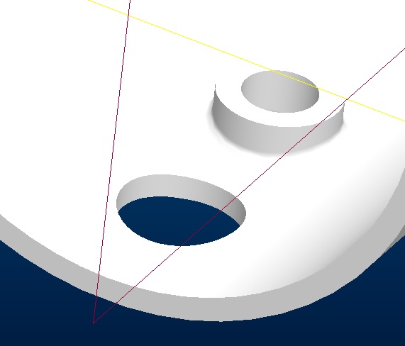
There is a family of tubes that are cut to a raw length. Then they are run through a press to add a stamped hole and a piercing that gets tapped. Currently the family is built around the second step in that the the main diameter of the tube is extruded and the the piercing and hole are added (negating the fact that they come from a pre-cut tube length).
I was going to brake these appart so that the BOM called a tube in an assembly and then I was going to add the piercing. I forgot one thing. You cannot add an extrude in an assembly (only a cut/extrude). Any thoughts or suggestions on how to procede?
Thanks, Dale
This thread is inactive and closed by the PTC Community Management Team. If you would like to provide a reply and re-open this thread, please notify the moderator and reference the thread. You may also use "Start a topic" button to ask a new question. Please be sure to include what version of the PTC product you are using so another community member knowledgeable about your version may be able to assist.
16 REPLIES 16
Feb 06, 2014
08:17 PM
- Mark as New
- Bookmark
- Subscribe
- Mute
- Subscribe to RSS Feed
- Permalink
- Notify Moderator
Please log in to access translation
Feb 06, 2014
08:17 PM
Why is it that the Pink Floyd's song The Wall comes to mind every time someone wants to do something only to get whacked with a ruler across the knuckles by the "teacher". 
It is so odd that PTC doesn't recognize the need to "re-strike"... a form operation that happens at a next level assembly. This is so common in the industry!
I have seen a tutorial on a progressive die tutorial from PTC. They make extensive use of merged features from one level to the next. I cannot wrap my head around the logic, but there it is.
Let us know what you come up with.
Feb 07, 2014
07:59 AM
- Mark as New
- Bookmark
- Subscribe
- Mute
- Subscribe to RSS Feed
- Permalink
- Notify Moderator
Please log in to access translation
Feb 07, 2014
07:59 AM
As for now, I will live to fight another day. Now I know why they didn't do that. We'll have a dumb BOM at that level for now and just keep it that way.
I let you know if I come across something else and can go from there.
Feb 11, 2014
10:02 AM
- Mark as New
- Bookmark
- Subscribe
- Mute
- Subscribe to RSS Feed
- Permalink
- Notify Moderator
Please log in to access translation
Feb 11, 2014
10:02 AM
Do you or any of your collegues have a suggestion about a way to add materail in an assembly (move material in this case)? If I form a tube by punching it with a press and get the boss on the inside while referencing it from a blank tube in an assembly.
Thanks, Dale
Feb 11, 2014
12:40 PM
- Mark as New
- Bookmark
- Subscribe
- Mute
- Subscribe to RSS Feed
- Permalink
- Notify Moderator
Please log in to access translation
Feb 11, 2014
12:40 PM
Good question, I can certainly ask around.
Feb 11, 2014
01:13 PM
- Mark as New
- Bookmark
- Subscribe
- Mute
- Subscribe to RSS Feed
- Permalink
- Notify Moderator
Please log in to access translation
Feb 11, 2014
01:13 PM
You can create the feature at the part level in the assembly and then suppress it at the part level. To show it at the assembly either create an explicit family table for the tube with the feature resumed or use feature flexibility to resume the feature at the assembly level. This method creates an external reference from the assembly to the part, but as long as PTC won't allow material additions anywhere except parts there isn't an easier method.
If you are using the same tube in a lot of places and don't want to end up with an endless feature tree, create separate parts that inherit the base tube and use those in the next assembly to capture the added features.
Feb 11, 2014
01:49 PM
- Mark as New
- Bookmark
- Subscribe
- Mute
- Subscribe to RSS Feed
- Permalink
- Notify Moderator
Please log in to access translation
Feb 11, 2014
01:49 PM
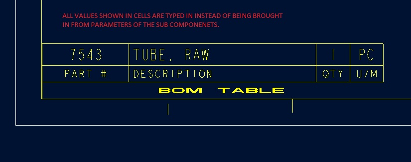
Currently it is suppressed in the basic cut tube and then unsuppressed at the "next" level. It is just that the BOM is a typed in BOM instead of calling the blank tube paramters (since they are the same paramaters used in the pierced tube - which are then used in the next level up).
Feb 11, 2014
02:16 PM
- Mark as New
- Bookmark
- Subscribe
- Mute
- Subscribe to RSS Feed
- Permalink
- Notify Moderator
Please log in to access translation
Feb 11, 2014
02:16 PM
"Currently it is suppressed in the basic cut tube and then unsuppressed at the "next" level. It is just that the BOM is a typed in BOM instead of calling the blank tube paramters (since they are the same paramaters used in the pierced tube - which are then used in the next level up)."
If this is a question or a problem to be resolved, how are you unsuppressing the features at the next level?
If you are just saying that you already do what I suggested to manage the features, then OK.
Feb 11, 2014
02:53 PM
- Mark as New
- Bookmark
- Subscribe
- Mute
- Subscribe to RSS Feed
- Permalink
- Notify Moderator
Please log in to access translation
Feb 11, 2014
02:53 PM
We currently have a family table and the features are suppressed in the blank tubes. The parameter for part number calls out the tube in the tube part and the peirced and tapped tube in its part.
What I was hoping to do was create an assembly that is the blank tube. After it is pierced and tapped, it becomes another part. So when creating a bill of material for the pierced and tapped part, I was hoping to have the pn in the BOM be the blank tube, and after words be a new number.
i.e. the blank tube is P/N 1234, the pierce and tapped is P/N 1235. I have a parameter in the family table for the part number (P/N), but if you call the part number in the pierced and tapped part, it will call it's own and not that of the blank tube.
Feb 11, 2014
03:29 PM
- Mark as New
- Bookmark
- Subscribe
- Mute
- Subscribe to RSS Feed
- Permalink
- Notify Moderator
Please log in to access translation
Feb 11, 2014
03:29 PM
Hi Dale,
Have you tried to filter the repeat region (your BOM) with the value of the user-defined parameter?
I don't work with family tables. I'm not sure if it could work this way.
Could you post an example model with a drawing?
Feb 11, 2014
03:50 PM
- Mark as New
- Bookmark
- Subscribe
- Mute
- Subscribe to RSS Feed
- Permalink
- Notify Moderator
Please log in to access translation
Feb 11, 2014
03:50 PM
Forgive my ingnorance, but can you do repeat regions without having an assembly?
As for the model and the drawing, the owner is the company is very particular, so I can do small screen dumps of not critical areas.
Thanks, Dale
Feb 13, 2014
11:53 AM
- Mark as New
- Bookmark
- Subscribe
- Mute
- Subscribe to RSS Feed
- Permalink
- Notify Moderator
Please log in to access translation
Feb 13, 2014
11:53 AM
Ok.
You could have a repeat region in the table like you have on the picture above.
All it takes is to have the part in a dummy assembly, and then have the repeat region defined such that it will reflect the conditions you have. Within repeat region it's possible to have the table cells display whatever information you may need.
I'd need to test it, but I guess in your part relations you could make checks for things like is the part taped, is the part pierced or whatever based on if these features are suppressed or not.
Then in the repeat region you could have relations to tell it to show whatever info you need depending on if the checks on part level are true or not.
Just have to try it. I'd make a dummy assembly and drawing by myself, but I guess I'm getting it all wrong.
Feb 11, 2014
03:51 PM
- Mark as New
- Bookmark
- Subscribe
- Mute
- Subscribe to RSS Feed
- Permalink
- Notify Moderator
Please log in to access translation
Feb 11, 2014
03:51 PM
I see what you want, but it's going to be rough going getting it.
For example, if this was a rivnut, you'd have no problems because it would work the way you want. It is impossible for it to both be altered and unaltered at the same time for the BOM and part drawing.
If the BOM is really desirable, then I'd look to making a little plug part that represents the boss you want and is then filtered out of the BOM. The little part would be seen in PDM as a part, but with a name like "Pierceandtap" so no one orders it.
Inheritance is an alternative that provides the 'make-from' traceability, but not the BOM support.
It's unlikely PTC will do anything about this, considering that the same case applies to creating weldments, for which they did not create a general-purpose solution to adding material in assemblies. Similarly conformal coating, plastisol dip, and various forms of encapsulation and potting. It will take AutoDesk or Siemens or Dassault Systèmes to sell a product that does this -and- start taking away a lot of PTC sales. THEN marketing will get the software developers to catch up.
Feb 11, 2014
02:22 PM
- Mark as New
- Bookmark
- Subscribe
- Mute
- Subscribe to RSS Feed
- Permalink
- Notify Moderator
Please log in to access translation
Feb 11, 2014
02:22 PM
Dale,
Currently adding material (or any feature) to parts in assembly context only is not supported.
Assembly-specifc context variations are available either as:
- Remove material - by assemly cut
- Change dimentions and parameters - by flexbile components/features
For the challange you are describing - there are two options you may consider:
1. If you wish to use *same* object for the different steps of the process (before/after adding the features) in different drawings - you can use part simprep and suppress the features as needed per drawing.
2. If you wish to have different object per step in the process - you can use Family-Table or Inhgeritance features.
We will consider in future releases to support part-level features addition in assembly context (similar to flexible components).
Hope that helps.
Feb 11, 2014
03:27 PM
- Mark as New
- Bookmark
- Subscribe
- Mute
- Subscribe to RSS Feed
- Permalink
- Notify Moderator
Please log in to access translation
Feb 11, 2014
03:27 PM
Dale, since often we want to make a raw material part and leave it alone (read only file) it is problematic having to change the common raw material file for every iteration in next level fabrication. An incidental file corruption can create havoc across a broad real product offering from any company.
I use to have this issue with O-rings fitting glands... they can be round, rectangular, odd, or squished. Similar issue as "wire". Often wires would have to be shaped to the particular application. There is no way I would want the master part file to be edited at every turn. These files have been there for decades and really should d-never- be altered.
The solution we came up with is that the file name (which is the part number) would be the original file name with a dash and the name of the file where it is used. It was a great convention if you don't have strict PDM structure rules. You would also assembly a blanked original part. to account for the item in the BOM. Any part number that did not comply with the part number format would be removed from the BOM.
For example, I have an o-ring p/n N23456 and an assembly C65413. If I need a specific shape of the o-ring, I create a part N23456-C65413. You can easily find the o-ring by the base number, and the where used by the second number. For those occasions where there are similar assemblies, the o-ring can be used with this same second number (where used in PDM will find it anywhere). The idea is that you won't change it willy nilly anyway. You would also assembly a blanked N23456 into C65413 to account for the part in BOM creation (PDM or Repeat Region Table).
In the case of the wire, the parts are all empty. This is the case of bulk material where you simply do not need any geometry in the part file. It becomes a placeholder.
In your case, tubing is a simple enough flexible component as long as it is not formed, bents, or otherwise changed in the manner you are proposing. Again, since the raw material is 99.9% stable in properties, there are limited reason you would want to assembly the raw material and then it at a new level for processing.
Similar scenario is sheetmetal. We re-invent the raw material at every instance. We do not stock a 4x8 sheet where a 4x4 or 2x4 sheet will suffice the same. We all form up a part based on a raw material and we account for it by either weight or unit length (rarely in the "Each"). But we have to account for that raw material in many cases. The above solution deals with this. We account for the raw material (the o-ring by p/n) and we create a geometric representation with a "placeholder" filename.
There has to be countless implementations of similar issues across the install base for all platforms. Things were a lot simpler "on the board".
Feb 11, 2014
03:50 PM
- Mark as New
- Bookmark
- Subscribe
- Mute
- Subscribe to RSS Feed
- Permalink
- Notify Moderator
Please log in to access translation
Feb 11, 2014
03:50 PM
The tubing that we buy are precut lengths and not just random 20's. So we order size specific parts that may (or may not) have secondary operations done to them depending upon what type of parts need to be made. And sometime they are not bought as blanks, but may have other things laser cut into them.
From a part-numbering standpoint, we do something similar for "specials" which are standard products modified to different lengths than the stadards that we offer. We just add the special length to the end of the part. These are typically cut from the next largest standard tube that we offer and for some special cases, we have a few random 20' for that extra long part.
The reason for wanting to assemble this into the secondary operations is that when I do have a special, I can modify the blank tube's length and it will propagate up the tree when I do a regen on the top level assembly. Currently with this and a couple of other operations, I have to modify 3-4 different parts to get the one length change that I want instead of doing one length change. This also reduces the potential for error when having to modify more then the one part.
Thanks for all of your input and discussions. It always helps to have fresh eyes to looks at what you are doing and see something that you may not be seeing it how to accomplish a task.
Feb 11, 2014
04:05 PM
- Mark as New
- Bookmark
- Subscribe
- Mute
- Subscribe to RSS Feed
- Permalink
- Notify Moderator
Please log in to access translation
Feb 11, 2014
04:05 PM
"Currently with this and a couple of other operations, I have to modify 3-4 different parts to get the one length change that I want instead of doing one length change."
For those who have a similar problem description I suggest the use of layouts.
They seem kind of awkward, but are a great solution where a bunch of parts/assemblies need to be coordinated about some set of dimensions. If you haven't used them, they are like a cocktail napkin with a crummy sketch and some dimensions. You refer to those dimensions via relations in other parts and tie all those dimensions together without tying the parts to each other or to some skeleton. Big advantage - the sketches are not to scale, so you can have a 1/32 hole 1/2 inch away from the end of a 10 mile long tube and see it. And you can add comments - add text and you can tell what the thing is for, unlike most all the rest of PTC software.
Many times, creating a layout should precede any other model making for complicate items.


