Community Tip - Did you get an answer that solved your problem? Please mark it as an Accepted Solution so others with the same problem can find the answer easily. X
- Community
- Creo+ and Creo Parametric
- 3D Part & Assembly Design
- Re: Placement and font size of annotation notes ma...
- Subscribe to RSS Feed
- Mark Topic as New
- Mark Topic as Read
- Float this Topic for Current User
- Bookmark
- Subscribe
- Mute
- Printer Friendly Page
Placement and font size of annotation notes made in the model are lost in drawing mode. How can make the drawing look like the model?
- Mark as New
- Bookmark
- Subscribe
- Mute
- Subscribe to RSS Feed
- Permalink
- Notify Moderator
Placement and font size of annotation notes made in the model are lost in drawing mode. How can make the drawing look like the model?
I'm using Creo Parametric 2.0. My model requires extensive labeling, which I made as annotation notes. When I go to drawing mode and display the annotations, they have all assumed the formatting given in the Active Drawing.dtl, the same formatting used for everything in the drawing. I'd like the annotation notes made in the model to remain in the same place and have the same font, size, line spacing, etc, when displayed in drawing mode. How do I do this? Should I have labeled my model some other way? How? Can the annotation notes be easily converted to this other text type? Thank you.
This thread is inactive and closed by the PTC Community Management Team. If you would like to provide a reply and re-open this thread, please notify the moderator and reference the thread. You may also use "Start a topic" button to ask a new question. Please be sure to include what version of the PTC product you are using so another community member knowledgeable about your version may be able to assist.
- Labels:
-
2D Drawing
- Mark as New
- Bookmark
- Subscribe
- Mute
- Subscribe to RSS Feed
- Permalink
- Notify Moderator
Yes, this would be nice, but it just doesn't work this way in Creo land. I get the impression that PTC meant for the "Annotation" tools found in modeling module to produce results that only stay and are viewed in the 3D model... the MBD panacea.
Importing model annotation notes and GD&T information into the 2D drawing module has never been a completely smooth experience. For example, sometimes you can't even show a model annotation on a drawing view because it's annotation plane isn't aligned to that of the view (though I think Creo 2.0 M200 has fixed some of these issues)
Anyway, if your deliverable is a drawing, shouldn't you be annotating your model in the drawing mode?
- Mark as New
- Bookmark
- Subscribe
- Mute
- Subscribe to RSS Feed
- Permalink
- Notify Moderator
Paul, Thanks for the info. I was arranging parts for a printed circuit board to communicate my electrical requirements to the PCB designer. I used the annotations to label the components and connector pins. It would have been impossible to do without labeling as I was laying out the parts. Creo Parametric is probably not the right tool for the job, but it's what we use here for all our mechanical design and my boss wants me to use it for this kind of work, too. With what I know now, I realize that I should have tried to make the labels part of the model (any suggestions for the best way to do this are very welcome). I still don't know if this will work, but I'm hoping the PCB designer will be able to import some format of my model into his layout software without having to manually recreate everything I did.
- Mark as New
- Bookmark
- Subscribe
- Mute
- Subscribe to RSS Feed
- Permalink
- Notify Moderator
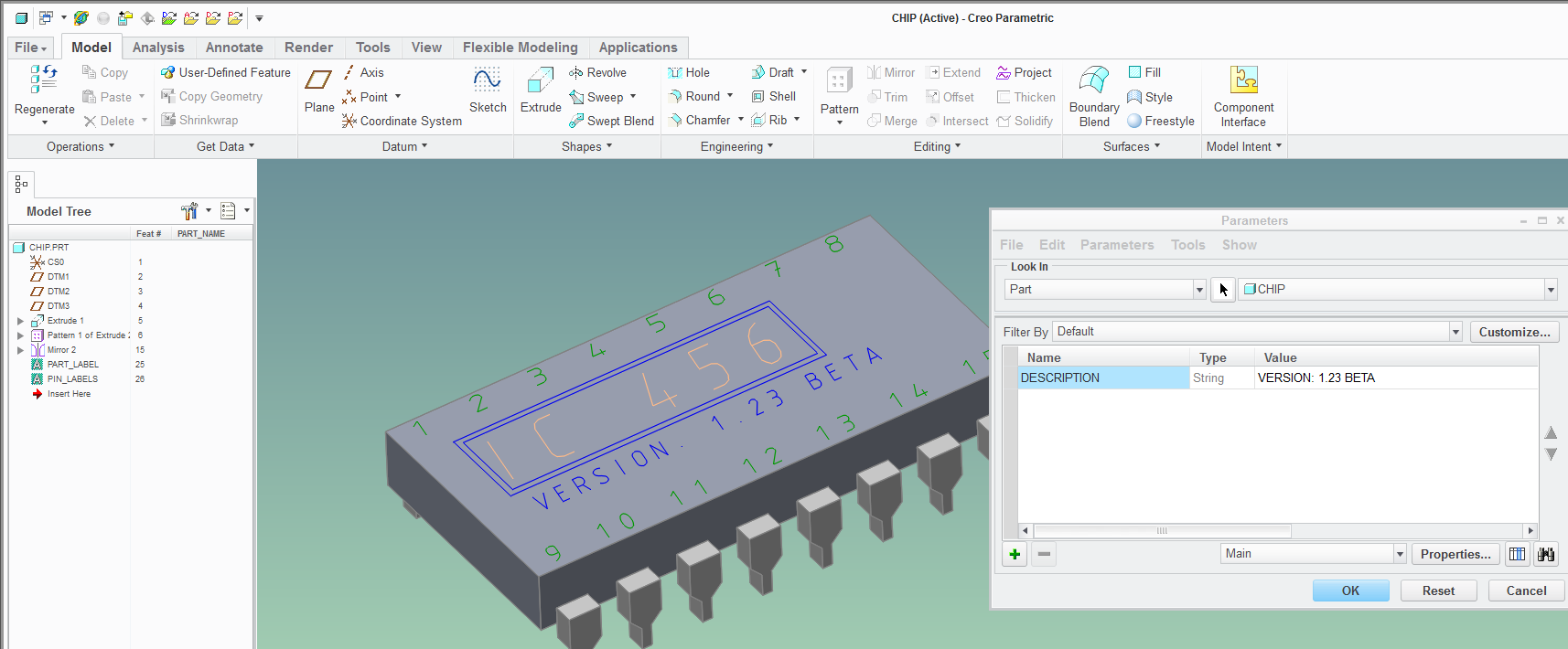
I'm not sure what your requirements are as far as your PCB designer being able to select the text you placed on your layout, but perhaps you could use under-constrained cosmetic sketches to display these kind of "decals" on your components:

I attach the Creo 2.0 model to see if this is something you could use.
Note that the text in sketches can be driven from user parameters, making editing the information quite easy.
Using cosmetic sketches allows you to work in the Under-constrained mode (look under setup section in the sketch ribbon) which basically means you can freehand things in (you can still constrain to align things). Also, you can also control the visibility of these labels by having the sketches go onto layers - and you can control these in the exported PDFs...
It sounds like you should really be using Creo Schematics, but you can do a lot to present the information well with the basic Creo package.
Just keep in mind that on the drawing these letters will not actually be a text entities, but just a bunch of lines!


