
Turn on suggestions
Auto-suggest helps you quickly narrow down your search results by suggesting possible matches as you type.
Showing results for
Please log in to access translation
Turn on suggestions
Auto-suggest helps you quickly narrow down your search results by suggesting possible matches as you type.
Showing results for
- Community
- Creo+ and Creo Parametric
- 3D Part & Assembly Design
- Re: Removing hidden welds in drawing sections?
Translate the entire conversation x
Please log in to access translation
Options
- Subscribe to RSS Feed
- Mark Topic as New
- Mark Topic as Read
- Float this Topic for Current User
- Bookmark
- Subscribe
- Mute
- Printer Friendly Page
Removing hidden welds in drawing sections?
Sep 10, 2014
04:49 AM
- Mark as New
- Bookmark
- Subscribe
- Mute
- Subscribe to RSS Feed
- Permalink
- Notify Moderator
Please log in to access translation
Sep 10, 2014
04:49 AM
Removing hidden welds in drawing sections?
(Creo Parametric 2)
I am having trouble with hiding/removing a hidden weld in a section in drawing view.
With a normal projected view, I would simply select "Yes" for "Hidden line removal for quilts" in the drawing view properties.
However when I have a section view, this option is greyed out, leaving welds which should be hidden visible.
How do I go about hiding these, either as a general setting for the view or as a manual deleting process?
Many thanks
This thread is inactive and closed by the PTC Community Management Team. If you would like to provide a reply and re-open this thread, please notify the moderator and reference the thread. You may also use "Start a topic" button to ask a new question. Please be sure to include what version of the PTC product you are using so another community member knowledgeable about your version may be able to assist.
23 REPLIES 23
Sep 10, 2014
01:05 PM
- Mark as New
- Bookmark
- Subscribe
- Mute
- Subscribe to RSS Feed
- Permalink
- Notify Moderator
Please log in to access translation
Sep 10, 2014
01:05 PM
The option has to be chosen when you create the section. I think it cannot be redefined after, but it is easy enough to create a new, coincident section and replace the existing one. Once replaced, delete the original section and then rename the new one to the original name.
Sep 11, 2014
03:37 AM
- Mark as New
- Bookmark
- Subscribe
- Mute
- Subscribe to RSS Feed
- Permalink
- Notify Moderator
Please log in to access translation
Sep 11, 2014
03:37 AM
Which option is it that has to be chosen when it is created?
I already tried simply selecting "Yes" for "hidden line removal for quilts", before creating the section, however it reverted to "No" when it greyed out..
Cheers
Sep 11, 2014
09:43 AM
- Mark as New
- Bookmark
- Subscribe
- Mute
- Subscribe to RSS Feed
- Permalink
- Notify Moderator
Please log in to access translation
Sep 11, 2014
09:43 AM
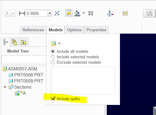
When you create the section in the model, there is the option to include quilts.
This is not the same as creating a section view in the drawing.
Sep 15, 2014
08:35 AM
- Mark as New
- Bookmark
- Subscribe
- Mute
- Subscribe to RSS Feed
- Permalink
- Notify Moderator
Please log in to access translation
Sep 15, 2014
08:35 AM
The thing is that I want some of the quilts to show, i.e. the ones which should be visible and not hidden behind a part. Is there no way to just hide the hidden ones?
Sep 15, 2014
10:31 AM
- Mark as New
- Bookmark
- Subscribe
- Mute
- Subscribe to RSS Feed
- Permalink
- Notify Moderator
Please log in to access translation
Sep 15, 2014
10:31 AM
http://www.mcadcentral.com/creo-drawing/16411-hlr-quilts-secti-n-view.html
"You need to cut the cross-section through "Model & Quilts". You will have to re-create your cross-section to select this option. And make sure you have "Remove quilts in total x-sec" set to yes in your DTL file. Then you should be able to seld "HLR for quilts".
Hope this helps."
http://www.eng-tips.com/viewthread.cfm?qid=289407
"Try implementing the config.pro option
HLR_FOR_QUILTS YES from Tools - Options
Check the following posted by user alibahadir at
Here is the solution for that offered by Ptc
Hidden line removal is known as not working in X-section views containing quilts which usually come with vendor parts.
In order to enable the HLR settings for X-section views (by the view settings or by the default settings with config.pro option 'hlr_for_quilts' set to YES), there are two requirements:
1. the dtl (drawing config.pro) setup option 'show_quilts_in_total_xsecs' MUST be set to 'yes' (the default is 'no')
2. the cross section MUST be created using the option 'Model & Qlts' for the cross section definition
Michael"
Sep 15, 2014
01:18 PM
- Mark as New
- Bookmark
- Subscribe
- Mute
- Subscribe to RSS Feed
- Permalink
- Notify Moderator
Please log in to access translation
Sep 15, 2014
01:18 PM
Simon, can you post an image of exactly what you are trying to do? I think we might be giving solutions for different situations.
Also, have you tried erasing the edges of the weld? edge display > erase line
Sep 15, 2014
02:47 PM
- Mark as New
- Bookmark
- Subscribe
- Mute
- Subscribe to RSS Feed
- Permalink
- Notify Moderator
Please log in to access translation
Sep 15, 2014
02:47 PM
I guess its not an edge either. Cosmetic features cannot be erased so you can remove all cosmetic features at once which include welds and threads. Otherwise, I still see no quick way to manage these without layers.
Attached is a short hap-hazard demonstration of one method to manage layers within the drawing only.
Note that I also included futile attempts to show what else could have been considered.
Finally, you will also note that layers play havoc with the weld symbol annotation. Once deleted, it should be recognized as being available for show-annotation... but it doesn't. Maybe only a bug in my M040 version of Creo 2.0
Sep 17, 2014
09:35 AM
- Mark as New
- Bookmark
- Subscribe
- Mute
- Subscribe to RSS Feed
- Permalink
- Notify Moderator
Please log in to access translation
Sep 17, 2014
09:35 AM
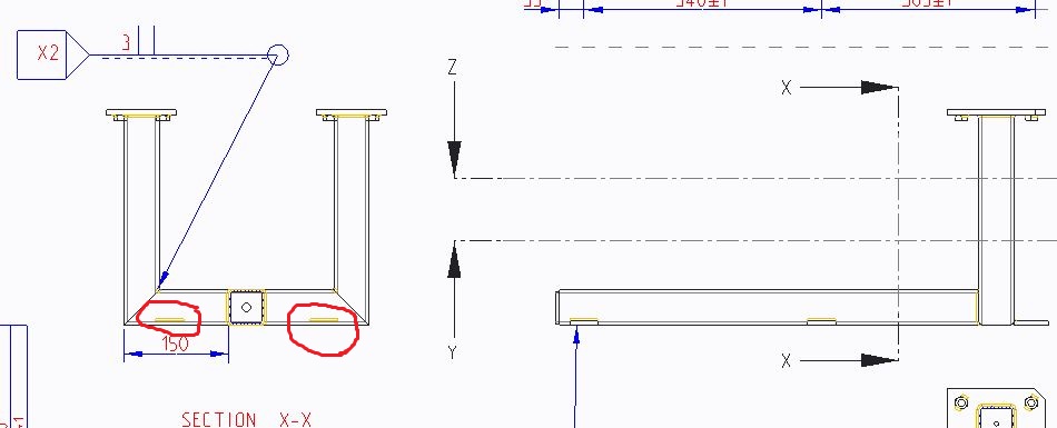
This is in third angle projection; the welds ringed in red should be hidden, however I want to keep the welds which SHOULD be visible, rather than hiding them all.
In the end, prior to pdf-ing it, I hid the welds in the model and manually drew in the weld fillet in the right hand view where they should be visible. A bit of a dirty work around, and not something I should have to do!
Sep 17, 2014
12:11 PM
- Mark as New
- Bookmark
- Subscribe
- Mute
- Subscribe to RSS Feed
- Permalink
- Notify Moderator
Please log in to access translation
Sep 17, 2014
12:11 PM
Oh, by hidden do you mean hidden line font? I thought we could do that. I will have another look.
Sep 17, 2014
03:32 PM
- Mark as New
- Bookmark
- Subscribe
- Mute
- Subscribe to RSS Feed
- Permalink
- Notify Moderator
Please log in to access translation
Sep 17, 2014
03:32 PM
Okay, this is still annoying but might work for you.
Nothing changes the line style view specific for a fillet weld that I tested. You only want it to show up that way in specific views, so changing the model's weld line style isn't a solution.
I went into the sketch mode in the drawing, toggled the parametric sketch option on and projected the weld edges I needed as hidden and once created (while still highlighted) I changed them to the Hidden line style. I then went through the drawing layer per view routine to hide the weld in that view.
When I changed the weld parameter, the drawing edges updated but when I added an additional segment, of course, I had to create the new edges again by projecting them. Using intent edges may solve this but in general, you get the idea.
Not being able to change the line style of the weld edges is somthing that appears to be a major oversight on PTC's part. Simon, have you considered asking tech support how PTC expects such a feature to be managed in drawings by opening a support case? If you have maintenance, you have every reason to get their input.
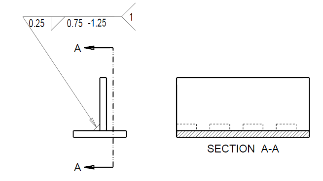
This is what I came up with... also notice the light weight line in the left side view for the weld... I suspect it should be the same line weight as solid edges.
Sep 18, 2014
04:11 AM
- Mark as New
- Bookmark
- Subscribe
- Mute
- Subscribe to RSS Feed
- Permalink
- Notify Moderator
Please log in to access translation
Sep 18, 2014
04:11 AM
You realize, per typical drafting standards, that welds are not depicted anyway? Just the weld symbol. It would be a nightmare amount of work to draw those things so the industry doesn't show welds at all. All that is needed is the label. PTC should rightfully say, don't show them at all on drawings.
I think there is a toggle to turn the weld quilts off and just have a line for the weld symbol. The terms 'Solid' and 'Light; show up in http://help.ptc.com/creo_hc/creo30_pma_hc/usascii/index.html#page/pma/welding/About_Conver_Welding_Geom_Types.html but it doesn't explain the difference. Another place calls them 'surface' and 'light.'
Sep 18, 2014
03:14 AM
- Mark as New
- Bookmark
- Subscribe
- Mute
- Subscribe to RSS Feed
- Permalink
- Notify Moderator
Please log in to access translation
Sep 18, 2014
03:14 AM
Antonius Dirriwachter wrote:
Oh, by hidden do you mean hidden line font? I thought we could do that. I will have another look.
I mean that the welds on the rear side of the workpiece, which the viewer has no line of sight to, should not be seen.
The welds on the front, or viewed side on, which which the viewer does have line of sight to should obviously remain visible.
Sep 18, 2014
03:19 AM
- Mark as New
- Bookmark
- Subscribe
- Mute
- Subscribe to RSS Feed
- Permalink
- Notify Moderator
Please log in to access translation
Sep 18, 2014
03:19 AM
Okay, I'm back to using layers then.
Sep 18, 2014
03:23 AM
- Mark as New
- Bookmark
- Subscribe
- Mute
- Subscribe to RSS Feed
- Permalink
- Notify Moderator
Please log in to access translation
Sep 18, 2014
03:23 AM
Fair enough, although it seems utterly daft that a function which is so easy to toggle in a general or projection view becomes such a pain in the backside as soon as you turn the view into a section!
Sep 18, 2014
04:19 AM
- Mark as New
- Bookmark
- Subscribe
- Mute
- Subscribe to RSS Feed
- Permalink
- Notify Moderator
Please log in to access translation
Sep 18, 2014
04:19 AM
Did you ever create a section in the assembly with Model & Quilts selected? That's what is supposed to trim out the Quilts that aren't supposed to be seen.
Sep 18, 2014
11:55 AM
- Mark as New
- Bookmark
- Subscribe
- Mute
- Subscribe to RSS Feed
- Permalink
- Notify Moderator
Please log in to access translation
Sep 18, 2014
11:55 AM
Doesn't that just section the quilts the cross section cuts through, and the quilts in front of the cross section?
I'll give that another try.
Sep 18, 2014
12:01 PM
- Mark as New
- Bookmark
- Subscribe
- Mute
- Subscribe to RSS Feed
- Permalink
- Notify Moderator
Please log in to access translation
Sep 18, 2014
12:01 PM
I asked, because I have done a lot of sections with quilts in them using the Model and Quilts option and it always came out OK. Maybe Simon used it and it didn't work for some reason, but I didn't see that he says so one way or the other.
Sep 18, 2014
12:27 PM
- Mark as New
- Bookmark
- Subscribe
- Mute
- Subscribe to RSS Feed
- Permalink
- Notify Moderator
Please log in to access translation
Sep 18, 2014
12:27 PM
I'll be darned! Yes, this also hides the quilts in front of the cross section view if they are hidden.
Unfortunately, it also erases the ones that should be visible.
I cannot weigh in on the welds when it comes to standards. I just make sure it is clear on drawings. Ground seam welds are always a challenge when it comes to the fab drawing and subsequent assemblies. Since this is only a rare requirement, I model the weld as a separate feature in an assembly.
Sep 10, 2014
01:06 PM
- Mark as New
- Bookmark
- Subscribe
- Mute
- Subscribe to RSS Feed
- Permalink
- Notify Moderator
Please log in to access translation
Sep 10, 2014
01:06 PM
Welcome to the forum, Simon.
Welds being quilts is problematic no matter how you deal with them.
I don't use the intelligent layers and I rarely need to show model quilts in any view... except for the weld that may be required in only one view (spot or seem welds).
However, I do create a layer in the model called HIDE_WELDS to specifically turn these layers of in specific views. By managing layers by view, or drawing, there are fewer issues with model layer states. I suppose you could reverse this and use SHOW_WELDS but that means your model will have to hide them by default. I never liked things popping into drawings that are suppose to be hidden. All too often I check a drawing that has been ECO'd only to find a completely unrelated view change visibility of features.
Nov 28, 2014
09:57 AM
- Mark as New
- Bookmark
- Subscribe
- Mute
- Subscribe to RSS Feed
- Permalink
- Notify Moderator
Please log in to access translation
Nov 28, 2014
09:57 AM
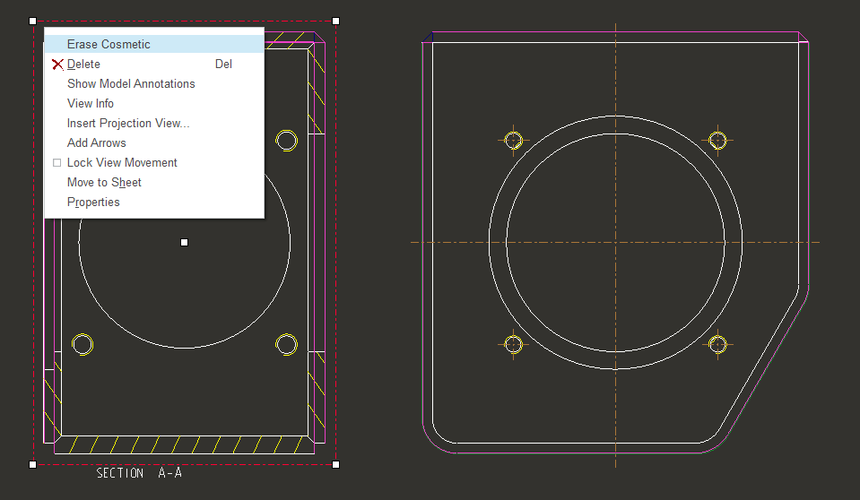
Hi,
try right click on the view, and select "erase cosmetic"
Jan 06, 2015
06:33 AM
- Mark as New
- Bookmark
- Subscribe
- Mute
- Subscribe to RSS Feed
- Permalink
- Notify Moderator
Please log in to access translation
Jan 06, 2015
06:33 AM
Fernando Lopes,
Thanks, it's so useful for me. I was searching for this command.
Jul 22, 2016
03:13 AM
- Mark as New
- Bookmark
- Subscribe
- Mute
- Subscribe to RSS Feed
- Permalink
- Notify Moderator
Please log in to access translation
Jul 22, 2016
03:13 AM
Hi all,
I use WF 5 and in the case you have a section with weld feature, the only manner to to hide them is to create a layer with the welding feature inside and then hide the layer referred with that particular view.
Bye
Jul 22, 2016
03:38 AM
- Mark as New
- Bookmark
- Subscribe
- Mute
- Subscribe to RSS Feed
- Permalink
- Notify Moderator
Please log in to access translation
Jul 22, 2016
03:38 AM
Sorry, in the photo I've searched for "welding feature". It works but if you hide the feature I can't visualize the welding note.
You have to search for "Fillet weld".
Bye


