Community Tip - Did you get an answer that solved your problem? Please mark it as an Accepted Solution so others with the same problem can find the answer easily. X
- Community
- Creo+ and Creo Parametric
- 3D Part & Assembly Design
- Re: Roller Chain in Creo 2.0
- Subscribe to RSS Feed
- Mark Topic as New
- Mark Topic as Read
- Float this Topic for Current User
- Bookmark
- Subscribe
- Mute
- Printer Friendly Page
Roller Chain in Creo 2.0
- Mark as New
- Bookmark
- Subscribe
- Mute
- Subscribe to RSS Feed
- Permalink
- Notify Moderator
Roller Chain in Creo 2.0
Hi All,
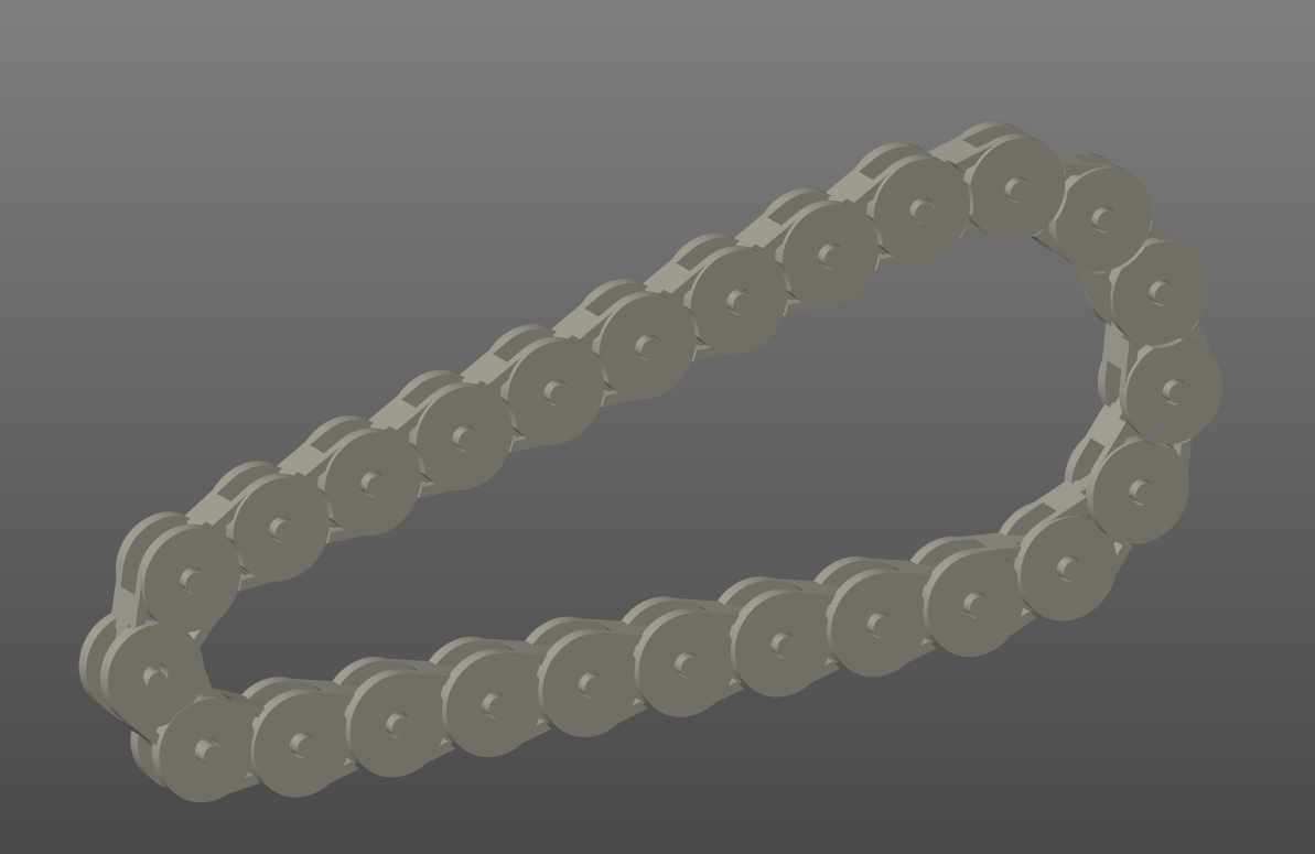
I am having hard time in sketching roller chain in creo 2.0, what I have done draw the sketch and placing the datum points on sketch So I can import the links. Once after placing Datum Points 1 and 2, when used Curve pattern I am getting pattern drawn offset from sketch, It is coming somehow offset the sketch.
It may be due to I am creating a patter of 2 datum points or could be the other reason.
If you guide me, it would be highly appreciated.
This thread is inactive and closed by the PTC Community Management Team. If you would like to provide a reply and re-open this thread, please notify the moderator and reference the thread. You may also use "Start a topic" button to ask a new question. Please be sure to include what version of the PTC product you are using so another community member knowledgeable about your version may be able to assist.
- Labels:
-
General
- Mark as New
- Bookmark
- Subscribe
- Mute
- Subscribe to RSS Feed
- Permalink
- Notify Moderator
you are right, it appears because of the multiple points in one feature.
As shown on the attached screenshot, the problem is, that the starting point (A) of your pattern doesnt match the origin point (B) of the datum points if you use more than 1 point in a single feature. Y
ou can correct that issue by using an alternative origin point (found in options of the pattern feature) that matches the starting point of the pattern (A=B).
But you have to be aware about the limitations:
The orientation of the single features created by the pattern feature relates just to the orientation point in combination with the refernence curve used for the pattern. I marked the different pattern controlled datum points with numbers of the referenced origin points (also pattern controlled).
hope my explanations dont confuse you more than they help
- Mark as New
- Bookmark
- Subscribe
- Mute
- Subscribe to RSS Feed
- Permalink
- Notify Moderator
+1 on choosing an appropriate origin.
By default, Creo chooses the bounding box center of the feature, and only if that happens to be the same as the original location, will it distribute correctly.
Creo really should prompt for origin. When this happens on a very small scale, it is easy to miss the error until it's too late. Careful!
- Mark as New
- Bookmark
- Subscribe
- Mute
- Subscribe to RSS Feed
- Permalink
- Notify Moderator
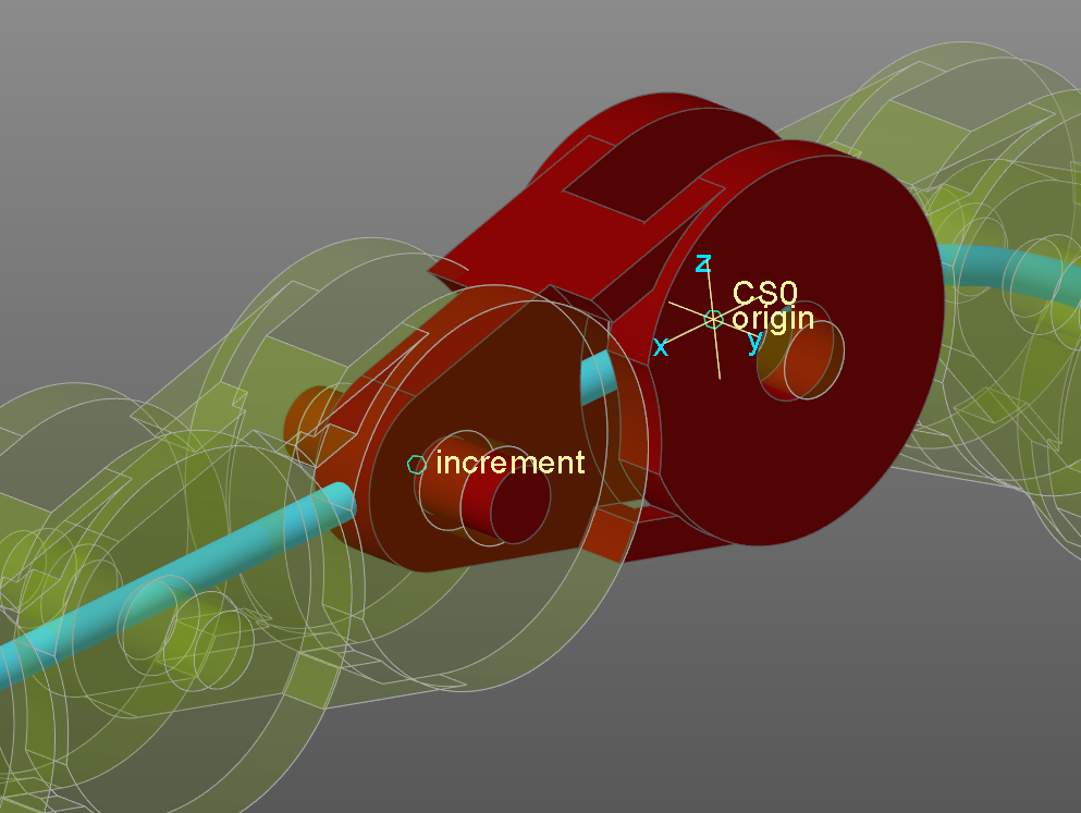
You can use a patterned datum point feature that contains 2 points. I used 2 that reference the entire curve and use "real" offset instead of "ratio". Also note, I created a copy of the sketched curve so that I could deliberately set the start (and end) point.
I then created a pattern of csys that have their origin at the first point, x axis pointing at the second point and the y axis pointing normal to the mid-plane.
Assembling the links now to the coordinate systems is reliable and much more obvious.


