
Turn on suggestions
Auto-suggest helps you quickly narrow down your search results by suggesting possible matches as you type.
Showing results for
Please log in to access translation
Turn on suggestions
Auto-suggest helps you quickly narrow down your search results by suggesting possible matches as you type.
Showing results for
Community Tip - When posting, your subject should be specific and summarize your question. Here are some additional tips on asking a great question. X
- Community
- Creo+ and Creo Parametric
- 3D Part & Assembly Design
- Re: Rotating Helical Curve from XY plane to XZ pla...
Translate the entire conversation x
Please log in to access translation
Options
- Subscribe to RSS Feed
- Mark Topic as New
- Mark Topic as Read
- Float this Topic for Current User
- Bookmark
- Subscribe
- Mute
- Printer Friendly Page
Rotating Helical Curve from XY plane to XZ plane
Apr 15, 2011
02:37 PM
- Mark as New
- Bookmark
- Subscribe
- Mute
- Subscribe to RSS Feed
- Permalink
- Notify Moderator
Please log in to access translation
Apr 15, 2011
02:37 PM
Rotating Helical Curve from XY plane to XZ plane
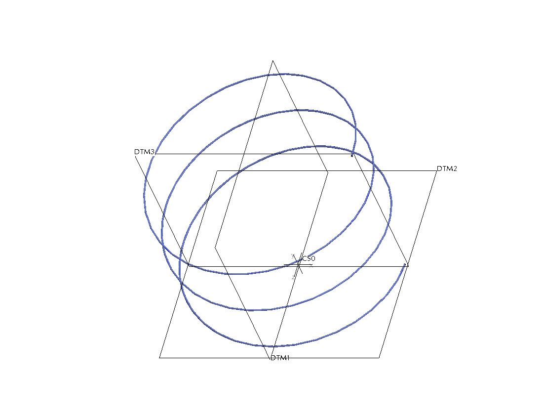
Using the cylindrical helical curve from equation option where you enter the "r, theta, and z" values, Is there any way to rotate the curve so that instead of the curve being in the XY plane it protrudes onto the XZ plane? I've attached an image that shows the curve on the default XY plane, I want the curv to run along the same axis as the threads on the part shown.
This thread is inactive and closed by the PTC Community Management Team. If you would like to provide a reply and re-open this thread, please notify the moderator and reference the thread. You may also use "Start a topic" button to ask a new question. Please be sure to include what version of the PTC product you are using so another community member knowledgeable about your version may be able to assist.
Labels:
- Labels:
-
General
25 REPLIES 25
Apr 16, 2011
02:06 AM
- Mark as New
- Bookmark
- Subscribe
- Mute
- Subscribe to RSS Feed
- Permalink
- Notify Moderator
Please log in to access translation
Apr 16, 2011
02:06 AM
You can try by creating another co-ordinate system with the desired Z direction. Select this coordinate system for your equation.
Apr 17, 2011
03:24 PM
- Mark as New
- Bookmark
- Subscribe
- Mute
- Subscribe to RSS Feed
- Permalink
- Notify Moderator
Please log in to access translation
Apr 17, 2011
03:24 PM
That is one way to do it that I hadn't thought about, Thanks
Apr 16, 2011
03:52 PM
- Mark as New
- Bookmark
- Subscribe
- Mute
- Subscribe to RSS Feed
- Permalink
- Notify Moderator
Please log in to access translation
Apr 16, 2011
03:52 PM
Or just change the equations appropriately; the helix axis doesn't have to be along the Z-axis.
Apr 17, 2011
03:22 PM
- Mark as New
- Bookmark
- Subscribe
- Mute
- Subscribe to RSS Feed
- Permalink
- Notify Moderator
Please log in to access translation
Apr 17, 2011
03:22 PM
I tried changing the equation by replacing Z = with X = or Y = and it didn't work. Is that the right idea? What would be the correct way to modify the equation?
Apr 17, 2011
05:05 PM
- Mark as New
- Bookmark
- Subscribe
- Mute
- Subscribe to RSS Feed
- Permalink
- Notify Moderator
Please log in to access translation
Apr 17, 2011
05:05 PM
For example:
x=2*cos(3*t*360)
y=3*t
z=2*sin(3*t*360)
Apr 17, 2011
05:12 PM
- Mark as New
- Bookmark
- Subscribe
- Mute
- Subscribe to RSS Feed
- Permalink
- Notify Moderator
Please log in to access translation
Apr 17, 2011
05:12 PM
Oops! I just reread your original post more closely; you were using Cylindrical coordinates, and I was thinking Cartesian. If you want to use Cylindrical coordinates, then Srinivasanlyer has given you the correct answer because Z is then the only axis available for cylindrical reference.
Jun 09, 2011
04:12 PM
- Mark as New
- Bookmark
- Subscribe
- Mute
- Subscribe to RSS Feed
- Permalink
- Notify Moderator
Please log in to access translation
Jun 09, 2011
04:12 PM
You can use D-H parameters (Denavit-Hartenberg aproximation) like if you use a robotic arm.
For example one rotation around X, one translation in X and one rotation of 90 degrees around X transform a single point in a circle.
If you repeat that (6 homogeneus matrix) you have a circular trayectory arround a circle (a torus coil).
x = c1*(l1 + l2*c2)
y = s1*(l1 + l2*c2)
z = l2*s2
can afect z to have an helical coil
If you repeat it again (9 homogeneus matrix) you can obtain a circle that follow a circle that follow the first circle (a coiled helix halo).
X = c1*(c2*(c3*l3+l2)+l1)-l3*s1*s3
y = c1*l3*s3+(c2*(c3*l3+l2)+l1)*s1
z = (c3*l3+l2)*s2
El mensaje fue editado por: Faustino Garcia
Jun 09, 2011
04:23 PM
- Mark as New
- Bookmark
- Subscribe
- Mute
- Subscribe to RSS Feed
- Permalink
- Notify Moderator
Please log in to access translation
Jun 09, 2011
04:23 PM
If you repeat it again (9 homogeneus matrix) you can obtain a circle that follow a circle that follow the first circle (a coiled helix halo).
X = c1*(c2*(c3*l3+l2)+l1)-l3*s1*s3
y = c1*l3*s3+(c2*(c3*l3+l2)+l1)*s1
z = (c3*l3+l2)*s2
El mensaje fue editado por: Faustino Garcia
Jun 09, 2011
05:03 PM
- Mark as New
- Bookmark
- Subscribe
- Mute
- Subscribe to RSS Feed
- Permalink
- Notify Moderator
Please log in to access translation
Jun 09, 2011
05:03 PM
Very interesting, so what then are the variable s and l and how do you define them? I'm in WF 4.0 so the .zip file doesn't work with my version.
Jun 09, 2011
05:25 PM
- Mark as New
- Bookmark
- Subscribe
- Mute
- Subscribe to RSS Feed
- Permalink
- Notify Moderator
Please log in to access translation
Jun 09, 2011
05:25 PM
s for sin
c for cos
l is length (in this case radio)
These are the equations.
Torus coil.
/* For cartesian coordinate system, enter parametric equation
/* in terms of t (which will vary from 0 to 1) for x, y and z
/* For example: for a circle in x-y plane, centered at origin
/* and radius = 4, the parametric equations will be:
/* x = 4 * cos ( t * 360 )
/* y = 4 * sin ( t * 360 )
/* z = 0
/*-------------------------------------------------------------------
/*coils
n=10
/*torus radio
l1 = 25
/*coil radio
l2 = 5
/*torus total angle
omega1 = 360
/*coils total angle
omega2 = n * omega1
/* torus actual angle
teta1 = omega1*t
/*coils actual angle
teta2 = omega2*t
/* trigonometric simplifications
c1 = cos(teta1)
s1 = sin(teta1)
c2 = cos(teta2)
s2 = sin(teta2)
/* cartesian parameters
x = c1*(l1 + l2*c2)
y = s1*(l1 + l2*c2)
z = l2*s2
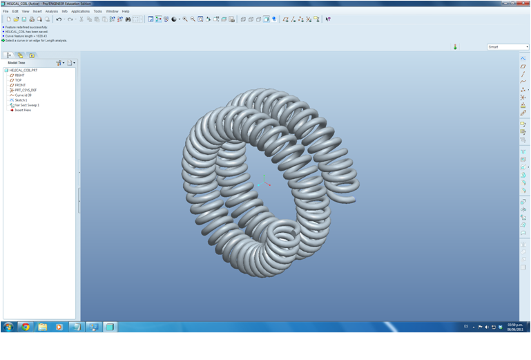
Helical coil.
/* For cartesian coordinate system, enter parametric equation
/* in terms of t (which will vary from 0 to 1) for x, y and z
/* For example: for a circle in x-y plane, centered at origin
/* and radius = 4, the parametric equations will be:
/* x = 4 * cos ( t * 360 )
/* y = 4 * sin ( t * 360 )
/* z = 0
/*-------------------------------------------------------------------
/*number of torus
n1 = 2
/*coils per torus
n2 = 40
/*torus radio
l1 = 10
/*coil radio
l2 = 2
/*torus total angle
omega1 = n1 * 360
/*coils total angle
omega2 = n2 * omega1
/* torus actual angle
teta1 = omega1*t
/*coils actual angle
teta2 = omega2*t
/* trigonometric simplifications
c1 = cos(teta1)
s1 = sin(teta1)
c2 = cos(teta2)
s2 = sin(teta2)
/* cartesian parameters
x = c1*(l1 + l2*c2)
y = s1*(l1 + l2*c2)
/* z = l2*s2
/* every torus turn z value afected by 3 coil radus
z = (l2*s2)+3*n1*l2*t
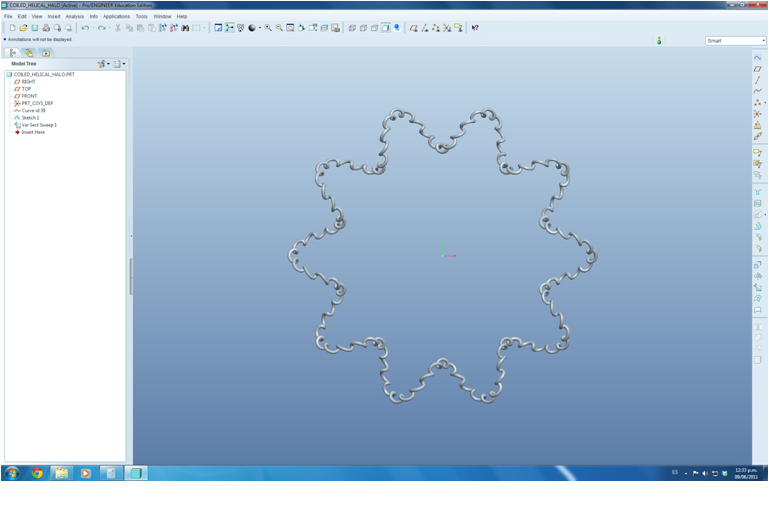
Coiled helical halo.
/* For cartesian coordinate system, enter parametric equation
/* in terms of t (which will vary from 0 to 1) for x, y and z
/* For example: for a circle in x-y plane, centered at origin
/* and radius = 4, the parametric equations will be:
/* x = 4 * cos ( t * 360 )
/* y = 4 * sin ( t * 360 )
/* z = 0
/*-------------------------------------------------------------------
/*helix waves in halo
n2 = 10
/*coils per helix
n3 = 10
/*halo radio
l1 = 36
/*helix radio
l2 = 6
/*coil radio
l3 = 1
/*halo total angle or speed
omega1 = 360
/*helix total angle or speed
omega2 = n2 * omega1
/*coil total angle or speed
omega3 = n3 * omega2
/* halo actual angle
teta1 = omega1*t
/*helix actual angle
teta2 = omega2*t
/*coil actual angle
teta3 = omega3*t
/* trigonometric simplifications
c1 = cos(teta1)
s1 = sin(teta1)
c2 = cos(teta2)
s2 = sin(teta2)
c3 = cos(teta3)
s3 = sin(teta3)
/* cartesian parameters
X = c1*(c2*(c3*l3+l2)+l1)-l3*s1*s3
y = c1*l3*s3+(c2*(c3*l3+l2)+l1)*s1
z = (c3*l3+l2)*s2
Those are the matrix of homogeneus transformation.
/* [wxMaxima batch file version 1] [ DO NOT EDIT BY HAND! ]*/
/* [ Created with wxMaxima version 11.04.0 ] */
/* [wxMaxima: input start ] */
rotz1: matrix(
[c1,-s1,0,0],
[s1,c1,0,0],
[0,0,1,0],
[0,0,0,1]
);
/* [wxMaxima: input end ] */
/* [wxMaxima: input start ] */
trasx1: matrix(
[1,0,0,l1],
[0,1,0,0],
[0,0,1,0],
[0,0,0,1]
);
/* [wxMaxima: input end ] */
/* [wxMaxima: input start ] */
rotx1: matrix(
[1,0,0,0],
[0,0,-1,0],
[0,1,0,0],
[0,0,0,1]
);
/* [wxMaxima: input end ] */
/* [wxMaxima: input start ] */
rotz2: matrix(
[c2,-s2,0,0],
[s2,c2,0,0],
[0,0,1,0],
[0,0,0,1]
);
/* [wxMaxima: input end ] */
/* [wxMaxima: input start ] */
trasx2: matrix(
[1,0,0,l2],
[0,1,0,0],
[0,0,1,0],
[0,0,0,1]
);
/* [wxMaxima: input end ] */
/* [wxMaxima: input start ] */
rotx2: matrix(
[1,0,0,0],
[0,0,1,0],
[0,-1,0,0],
[0,0,0,1]
);
/* [wxMaxima: input end ] */
/* [wxMaxima: input start ] */
p2: matrix(
[0],
[0],
[0],
[1]
);
/* [wxMaxima: input end ] */
/* [wxMaxima: input start ] */
rotz1.trasx1.rotx1.rotz2.trasx2.rotx2.p2;
/* [wxMaxima: input end ] */
/* [wxMaxima: input start ] */
rotz3: matrix(
[c3,-s3,0,0],
[s3,c3,0,0],
[0,0,1,0],
[0,0,0,1]
);
/* [wxMaxima: input end ] */
/* [wxMaxima: input start ] */
trasx3: matrix(
[1,0,0,l3],
[0,1,0,0],
[0,0,1,0],
[0,0,0,1]
);
/* [wxMaxima: input end ] */
/* [wxMaxima: input start ] */
rotx3: matrix(
[1,0,0,0],
[0,0,-1,0],
[0,1,0,0],
[0,0,0,1]
);
/* [wxMaxima: input end ] */
/* [wxMaxima: input start ] */
p3: matrix(
[0],
[0],
[0],
[1]
);
/* [wxMaxima: input end ] */
/* [wxMaxima: input start ] */
rotz1.trasx1.rotx1.rotz2.trasx2.rotx2.rotz3.trasx3.rotx3.p3;
/* [wxMaxima: input end ] */
/* Maxima can't load/batch files which end with a comment! */
"Created with wxMaxima"$
best regards.
Jun 10, 2011
03:49 PM
- Mark as New
- Bookmark
- Subscribe
- Mute
- Subscribe to RSS Feed
- Permalink
- Notify Moderator
Please log in to access translation
Jun 10, 2011
03:49 PM
I continue experiment and only have 3 solutions til now:
1. SrinivasanIyer solution of use another coordinate system.
2. David Butz solution of use a cartesian system definition, can use homogenius transformation too, is perfect as David Butz says.
3. Make the helical curve (or helical solid) in another part file and assemble both part files, if possible.
Best regards, all of you.
Sep 22, 2011
08:59 AM
- Mark as New
- Bookmark
- Subscribe
- Mute
- Subscribe to RSS Feed
- Permalink
- Notify Moderator
Please log in to access translation
Sep 22, 2011
08:59 AM
Here is solutions if you want to use other technique: http://communities.ptc.com/blogs/vpalffy/2011/02/09/user-defined-springs
Vladimir 
Best Regards,
Vladimir Palffy
Vladimir Palffy
Sep 22, 2011
03:00 PM
- Mark as New
- Bookmark
- Subscribe
- Mute
- Subscribe to RSS Feed
- Permalink
- Notify Moderator
Please log in to access translation
Sep 22, 2011
03:00 PM
I agree with Vladimir.
Use Trajpar and never look back! 
That way your helix can adapt to changes in model and you can make basicly any wierd helical thing.
Sep 22, 2011
04:20 PM
- Mark as New
- Bookmark
- Subscribe
- Mute
- Subscribe to RSS Feed
- Permalink
- Notify Moderator
Please log in to access translation
Sep 22, 2011
04:20 PM
The rounded square section coil looks so PRO!!, the heart is nice too. Excellent command, excellent comment. Thanks.
Sep 23, 2011
03:15 AM
- Mark as New
- Bookmark
- Subscribe
- Mute
- Subscribe to RSS Feed
- Permalink
- Notify Moderator
Please log in to access translation
Sep 23, 2011
03:15 AM
You are welcome. Thank you too 
Vladimir
Best Regards,
Vladimir Palffy
Vladimir Palffy
Oct 13, 2011
06:32 PM
- Mark as New
- Bookmark
- Subscribe
- Mute
- Subscribe to RSS Feed
- Permalink
- Notify Moderator
Please log in to access translation
Oct 13, 2011
06:32 PM
How about this for fun? 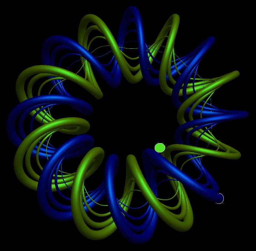
Oct 11, 2013
03:14 AM
- Mark as New
- Bookmark
- Subscribe
- Mute
- Subscribe to RSS Feed
- Permalink
- Notify Moderator
Please log in to access translation
Oct 11, 2013
03:14 AM
beautiful
tell me how make this type item
i wating your answer
Oct 13, 2011
06:42 PM
- Mark as New
- Bookmark
- Subscribe
- Mute
- Subscribe to RSS Feed
- Permalink
- Notify Moderator
Please log in to access translation
Oct 13, 2011
06:42 PM
Maybe this one?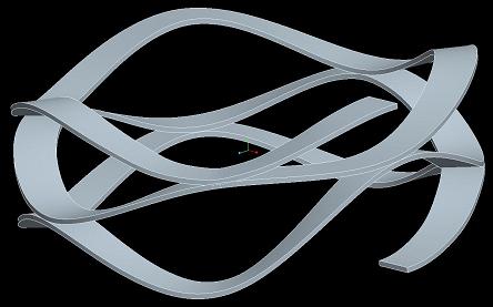
Oct 13, 2011
06:44 PM
- Mark as New
- Bookmark
- Subscribe
- Mute
- Subscribe to RSS Feed
- Permalink
- Notify Moderator
Please log in to access translation
Oct 13, 2011
06:44 PM
This?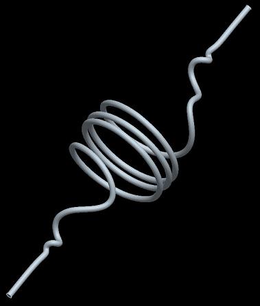
Oct 13, 2011
06:46 PM
- Mark as New
- Bookmark
- Subscribe
- Mute
- Subscribe to RSS Feed
- Permalink
- Notify Moderator
Please log in to access translation
Oct 13, 2011
06:46 PM
Maybe even this?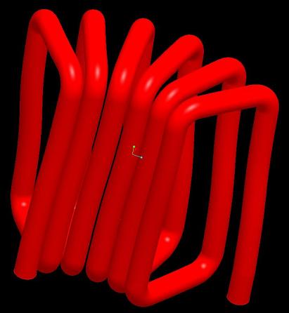
Oct 13, 2011
06:48 PM
- Mark as New
- Bookmark
- Subscribe
- Mute
- Subscribe to RSS Feed
- Permalink
- Notify Moderator
Please log in to access translation
Oct 13, 2011
06:48 PM
Even this perhaps? Oh, the FUN you can have! 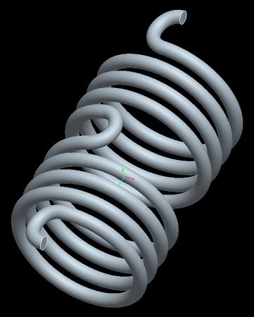
Dec 12, 2011
02:08 PM
- Mark as New
- Bookmark
- Subscribe
- Mute
- Subscribe to RSS Feed
- Permalink
- Notify Moderator
Please log in to access translation
Dec 12, 2011
02:08 PM
Hmm... so on this last one Frank, what are you using for the very first and last "hook" at the end of your helical spring? I have my own technique for achieving this, but I'm curious how you built yours.
Dec 21, 2011
09:52 AM
- Mark as New
- Bookmark
- Subscribe
- Mute
- Subscribe to RSS Feed
- Permalink
- Notify Moderator
Please log in to access translation
Dec 21, 2011
09:52 AM
The end and middle hooks are all cylindrical like the body of the spring itself instead of planar in the above torsional spring. This model was actually the easiest. In the red coil (which is actually the winding of an air-core ferric electrical part) the ends are both forced to be normal to a plane. The example above that has a constantly-changing radius, pitch, diameter, and reverses helical rotation twice. For the Smalley wave spring, their models suck, and i thought I'd make one that represents the true geometry. With the exception of the top coil that spirals inside itself (actually the toughest model to solve though easy to make if that makes any sense) these models were all made at least 12 years ago. I believe my e-mail is listed if you'd like to contact me about them.
Dec 22, 2011
05:23 PM
- Mark as New
- Bookmark
- Subscribe
- Mute
- Subscribe to RSS Feed
- Permalink
- Notify Moderator
Please log in to access translation
Dec 22, 2011
05:23 PM
Thanks for the extra information Frank.
Personally I love modeling springs and weird helical surfaces with complex transitions. After your explanation and some careful examination, I'm confident I understand how you did them.
I think I was outsmarting myself. The one that reverses rotation twice had me stumped. I can do it in two features easily enough or by merging two trajectories into one and then sweeping the solid. I guess I looked at it and thought you managed a direction-reversing coil all in one feature. Was it just two trajectories back to back or did you indeed figure out some clever mathematical way to reverse direction?
Thanks again!
-Brian
Dec 23, 2011
09:55 AM
- Mark as New
- Bookmark
- Subscribe
- Mute
- Subscribe to RSS Feed
- Permalink
- Notify Moderator
Please log in to access translation
Dec 23, 2011
09:55 AM
For all those springs, there is only a single continuous trajectory, even for the reversals of rotation, and even for the Smalley spring, which is perfectly cylindrical on it's inner and outer surfaces. The red coil was a trajectory that is the intersection of 2 surfaces, but it is still a single trajectory, even with the ends normal to a plane on the bottom. It was part of a coil and I did it just for fun, I just didn't bother to add the short straight leads for the thru-hole solder joint to the PCB. I have a technique where I can model spring ends normal to or parallel to the cylindrical axis of a spring on one trajectory feature. And, best of all, there is no math involved, just trajpar.
So, how did I do the torsional spring ends?


