
Turn on suggestions
Auto-suggest helps you quickly narrow down your search results by suggesting possible matches as you type.
Showing results for
Please log in to access translation
Turn on suggestions
Auto-suggest helps you quickly narrow down your search results by suggesting possible matches as you type.
Showing results for
Community Tip - You can Bookmark boards, posts or articles that you'd like to access again easily! X
- Community
- Creo+ and Creo Parametric
- 3D Part & Assembly Design
- Re: Section not showing correctly on drawing when ...
Translate the entire conversation x
Please log in to access translation
Options
- Subscribe to RSS Feed
- Mark Topic as New
- Mark Topic as Read
- Float this Topic for Current User
- Bookmark
- Subscribe
- Mute
- Printer Friendly Page
Section not showing correctly on drawing when through an axis
May 07, 2015
10:13 AM
- Mark as New
- Bookmark
- Subscribe
- Mute
- Subscribe to RSS Feed
- Permalink
- Notify Moderator
Please log in to access translation
May 07, 2015
10:13 AM
Section not showing correctly on drawing when through an axis
I just went through a problem one of my users encountered again. It's something that pops up on occasion but never with any sort of regularity, consistency or repeatability.
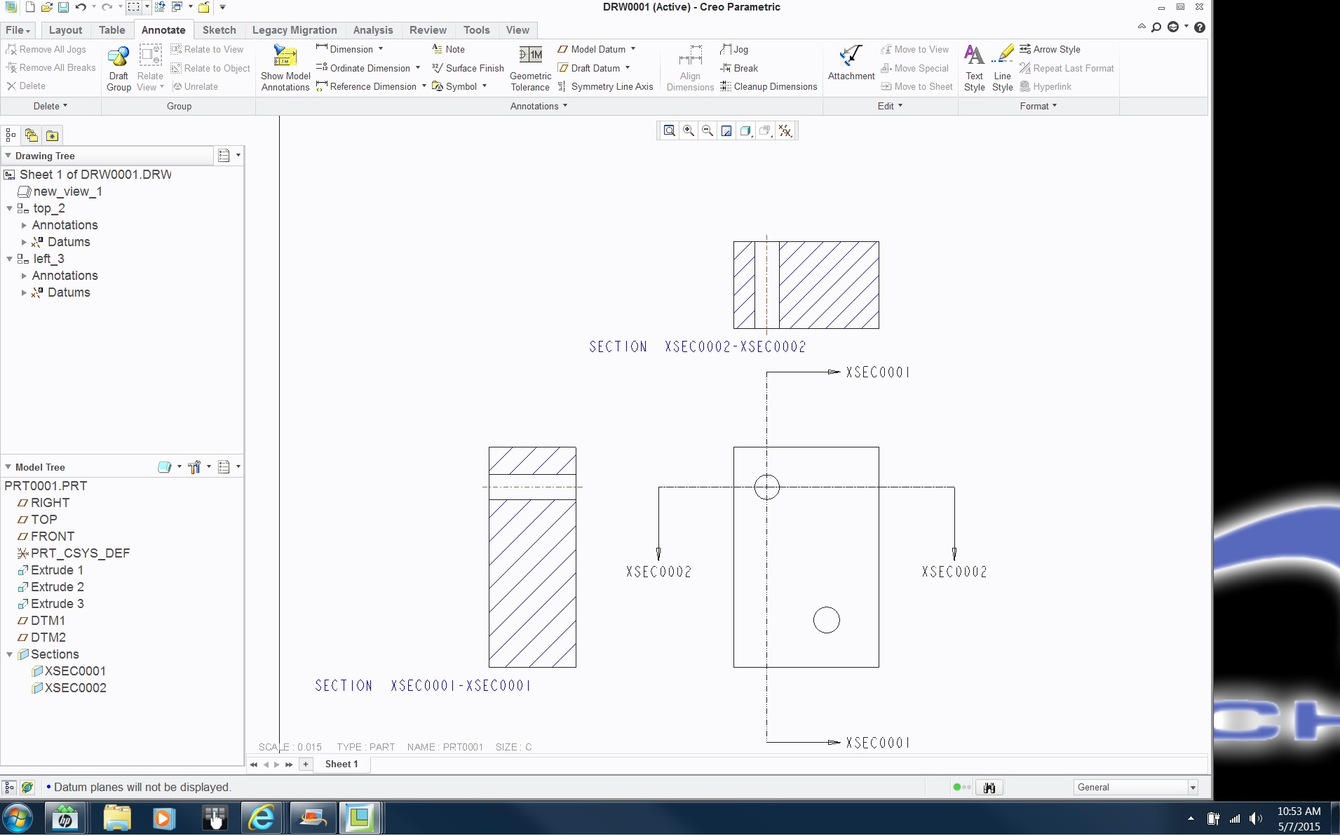
He created a section in his model that cuts through the center of a hole (or a hole-shaped extrude). In the model the section displays 100% correctly. However, when placing a drawing view, the section does not behave correctly. No matter what actions taken to try to resolve this the x-hatching does not display properly and it appears the section is cutting through a different location.
The only fix appears to be moving the x-section datum plane so it's .005" off the axis of the hole it goes through. Once that is done, everything looks the way it should.
Things we've tried that did not correct the problem:
- redefine the x-section datum plane side (flip the datum arrow)
- recreate the x-section datum plane
- flip the section in the model
- flip the section in the drawing
- change to an offset section that references the hole/extrude axis
- change to an offset section that does not reference the hole/extrude axis
- create the hole/extrude axis as a child of the x-section datum plane
- create the x-section datum as a child of the hole/extrude axis
- create the x-section datum and the hole/extrude completely independent of each other (no parent/child relationship)
Action taken to correct the problem
- create the section so it does NOT go through the axis -- we offset it by .005" and it worked properly
Generally this solution allows an acceptable drawing to be created, especially if it's possible to use driving/shown dimensions for the features shown.
However, I'm wondering if there is a solution that doesn't involve faking out the system. This is a problem that I've seen since around the beginning of Wildfire.
As mentioned, repeatability is an issue. Every time I've tried to recreate the problem -- because that's the first thing tech support is going to ask for -- the sections work perfectly. I can't send the actual drawing/part files due to restrictions (and so far it hasn't been worth the paperwork trouble). It also happens so rarely that users generally forget about it and this time it took me some time to remember the trick to fixing it.
So, has anyone else seen this behavior and is there a solution I'm overlooking?
This thread is inactive and closed by the PTC Community Management Team. If you would like to provide a reply and re-open this thread, please notify the moderator and reference the thread. You may also use "Start a topic" button to ask a new question. Please be sure to include what version of the PTC product you are using so another community member knowledgeable about your version may be able to assist.
Labels:
- Labels:
-
General
13 REPLIES 13
May 07, 2015
10:19 AM
- Mark as New
- Bookmark
- Subscribe
- Mute
- Subscribe to RSS Feed
- Permalink
- Notify Moderator
Please log in to access translation
May 07, 2015
10:19 AM
Show Model Annotations "axis" doesn't work either?
May 07, 2015
10:42 AM
- Mark as New
- Bookmark
- Subscribe
- Mute
- Subscribe to RSS Feed
- Permalink
- Notify Moderator
Please log in to access translation
May 07, 2015
10:42 AM
The problem is an evaluation problem. It doesn't have as much to do with the axis as it does that cylinders have two surfaces with joints between them and the cross-section software is having trouble in figuring this out. Since the joints share common vertices the intersection calculation can't determine for certain which of the two surfaces have priority. When you offset the section by .005 you are moving the evaluation away from that joint.
The problem has been around since rev 13.
AFAIK there is no general fix; moving the section plane is the most frequent choice, but maybe accuracy changes would also work, though it causes the entire model to be re-evaluated.
If you turn the Sketcher section (not cross section) orientation a few degrees, 90 seems like a good value, the joint in the cylinder will be rotated and the section plane won't intersect it, but that's a lot of trouble; the offset is easier.
May 07, 2015
10:43 AM
- Mark as New
- Bookmark
- Subscribe
- Mute
- Subscribe to RSS Feed
- Permalink
- Notify Moderator
Please log in to access translation
May 07, 2015
10:43 AM
Does an accuracy change fix it?
May 07, 2015
12:23 PM
- Mark as New
- Bookmark
- Subscribe
- Mute
- Subscribe to RSS Feed
- Permalink
- Notify Moderator
Please log in to access translation
May 07, 2015
12:23 PM
It was never my choice. I just moved the section a little bit. The reason I think accuracy won't work is that the vertices are still going to be coincident, so the section will still have the chance to intersect both at the same time and be unable to decide which one is in front of the other.
May 07, 2015
10:58 AM
- Mark as New
- Bookmark
- Subscribe
- Mute
- Subscribe to RSS Feed
- Permalink
- Notify Moderator
Please log in to access translation
May 07, 2015
10:58 AM
Don,
Sections cut in both directions eliminating the "both halves vertices" issue with Shown Axes in the sections.
Not sure what is up on your side. "Shown" axes should have no real link back to the cylinder halves. I know there have been some long running view dependent issues, but for simple extruded holes, not so much. This should especially be true if the axes are created in the model on the cylinder after the fact.
May 07, 2015
01:05 PM
- Mark as New
- Bookmark
- Subscribe
- Mute
- Subscribe to RSS Feed
- Permalink
- Notify Moderator
Please log in to access translation
May 07, 2015
01:05 PM
It's not the shown axes. Showing or not showing them doesn't affect the error in any way. It's the axis created by the hole feature or a circular extrude feature that I was referring to.
Without testing to verify, David's reasoning makes the most sense with the vertices all lining up. Just a shame that PTC hasn't figured out how to fix it in all this time.
May 07, 2015
01:24 PM
- Mark as New
- Bookmark
- Subscribe
- Mute
- Subscribe to RSS Feed
- Permalink
- Notify Moderator
Please log in to access translation
May 07, 2015
01:24 PM
THE DREADED HOLE FEATURE!
May 07, 2015
02:54 PM
- Mark as New
- Bookmark
- Subscribe
- Mute
- Subscribe to RSS Feed
- Permalink
- Notify Moderator
Please log in to access translation
May 07, 2015
02:54 PM
Arrgghhh, I hate when this problem happens. We get it here generally on large assembly models. Something about that x-section that the drawing can't handle. We also do the minor offset to correct the issue usually. It always comes with a line in the message log Cross-section creation in view "right_16", on sheet 2, aborted.
This thread says it's an accuracy issue.Problem creating cross-section view in a drawing
Search for Cross-section creation aborted and you'll get a bunch of hits..
On PTC support, you'll get this one https://support.ptc.com/appserver/cs/view/solution.jsp?n=CS20807&art_lang=en&posno=1&q=Cross-section%20creation%20aborte…
that leads you to this one http://support.ptc.com/cs/cs_27/howto/vew543/vew543.htm
May 07, 2015
03:44 PM
- Mark as New
- Bookmark
- Subscribe
- Mute
- Subscribe to RSS Feed
- Permalink
- Notify Moderator
Please log in to access translation
May 07, 2015
03:44 PM
It doesn't abort the creation. It just doesn't show correctly. It allows the section to be created and applied to a view, it's just messed up.
May 07, 2015
03:05 PM
- Mark as New
- Bookmark
- Subscribe
- Mute
- Subscribe to RSS Feed
- Permalink
- Notify Moderator
Please log in to access translation
May 07, 2015
03:05 PM
Maybe I am just dumb....but isn't it easier to simply add an axis to the hole that is to be sectioned and then "show" it on the drawing? Even if you have 100 holes you most likely will section one of them and say "Typical". And/Or....even if you had 100 unique holes that require sections, adding an axis is ridiculously simple. In fact I would argue that is more simple than adding a plane and then backing it off .005".
Am I missing the boat?
May 07, 2015
03:41 PM
- Mark as New
- Bookmark
- Subscribe
- Mute
- Subscribe to RSS Feed
- Permalink
- Notify Moderator
Please log in to access translation
May 07, 2015
03:41 PM
Missing the ocean? Check.
There is no adding of an axis. There is no showing of an axis. The plane isn't for the axis, it's for creating a section in the model (View Manager). Pick a datum plane in the model tree, then pick View Manager > Sections > New etc. and you'll have a cross section in the model that uses that datum plane as the location of the section.
That section is then shown on the drawing. But, it doesn't show correctly once in a blue moon because the section happens to rest on the axis. Or, according to David's explanation, the axis and the edges of the hole shells are all lined up and Creo simply freaks out on occasion. And it happens even when the axis isn't referenced at all.
May 07, 2015
03:53 PM
- Mark as New
- Bookmark
- Subscribe
- Mute
- Subscribe to RSS Feed
- Permalink
- Notify Moderator
Please log in to access translation
May 07, 2015
03:53 PM
Yep...missing the ocean, Don. For the reason I call OCBS (Old Crusty Brain Syndrome) I missed the point in the original. I thought you were trying to see the axis in the section for dimensioning. Back to sleep now.
May 07, 2015
04:04 PM
- Mark as New
- Bookmark
- Subscribe
- Mute
- Subscribe to RSS Feed
- Permalink
- Notify Moderator
Please log in to access translation
May 07, 2015
04:04 PM
Something to try: File > Prepare > Drawing Properties > Detail Options, enter 'update_drawing' for the option name and 'all' for the value. Regenerate your drawing. That tells the drawing to update to all version-protected bug fixes. If that fixes it, then you can either do it that way (and inspect the drawing to be sure nothing changed that you'd rather didn't), or if you have an SPR filed for it, we can hunt down the precise versioned fix.


