Community Tip - Did you get called away in the middle of writing a post? Don't worry you can find your unfinished post later in the Drafts section of your profile page. X
- Community
- Creo+ and Creo Parametric
- 3D Part & Assembly Design
- Re: Shared Parameters
- Subscribe to RSS Feed
- Mark Topic as New
- Mark Topic as Read
- Float this Topic for Current User
- Bookmark
- Subscribe
- Mute
- Printer Friendly Page
Shared Parameters
- Mark as New
- Bookmark
- Subscribe
- Mute
- Subscribe to RSS Feed
- Permalink
- Notify Moderator
Shared Parameters
Hi all,
is it possible for 2 separate parts to share a parameter? That the value of the parameter could be changed in either part & would be updated in the other.
Working with Creo 2. I would want to achieve this using standard Creo functionality if possible.
Regards
John
This thread is inactive and closed by the PTC Community Management Team. If you would like to provide a reply and re-open this thread, please notify the moderator and reference the thread. You may also use "Start a topic" button to ask a new question. Please be sure to include what version of the PTC product you are using so another community member knowledgeable about your version may be able to assist.
- Labels:
-
General
- Mark as New
- Bookmark
- Subscribe
- Mute
- Subscribe to RSS Feed
- Permalink
- Notify Moderator
I understand it is like sharing a value of same cell in other file in Excel where we have the option to give the path of the file and cell. I dont know it is possible or not, but I appreciate it's a nice idea. All the other options for sharing paramter like making common assembly or using internet explorer i guess you already know.
- Mark as New
- Bookmark
- Subscribe
- Mute
- Subscribe to RSS Feed
- Permalink
- Notify Moderator
Yes it is possible using a feature called a notebook. When you start a new part notebook is on the the options. You create a parameter in the notebook and assign a value. You then have to declare the different parts to the notebook that you want to use the parameter. The parameters that you have setup in the notebook are then available in each of the parts that have been declared to the notebook. The value is then changed in the notebook and the changes are reflected in the parts. You may also have to use a relation to link dimensions etc to the parameter in the notebook.
- Mark as New
- Bookmark
- Subscribe
- Mute
- Subscribe to RSS Feed
- Permalink
- Notify Moderator
I get an error trying to create a Notebook:
This functionality requires one of: NOTEBOOK <= Yet another great example of PTC-itish
I can see how to do this if both parts are used in the same assembly at some level using the top down design references.
- Mark as New
- Bookmark
- Subscribe
- Mute
- Subscribe to RSS Feed
- Permalink
- Notify Moderator
Looks like you don't have a lisence for Notebook. This is what use to be a Layout.
- Mark as New
- Bookmark
- Subscribe
- Mute
- Subscribe to RSS Feed
- Permalink
- Notify Moderator
Hi Antonius,
both parts are used in the same assembly, perhaps you could explain. It would appear that NOTEBOOK is the old LAYOUT, either way, its an option not open to me, as i don't have a licence.
Regards
John
- Mark as New
- Bookmark
- Subscribe
- Mute
- Subscribe to RSS Feed
- Permalink
- Notify Moderator
Top down design means you start with the assembly and your parts can reference features from each other. From the assembly level, you can make relations that use parameters from other parts.
This is one of the powers that Pro/E has had from the beginning but it also has pitfalls. I am ceretain that things like notebook and layout draw from this power but now that it is an extention product, old school works well.
The main thing to remember is that parts now become dependent on the assembly being loaded for certain operations. Often, this becomes an enterprise decision as to whether employees use this concept or not. Breaking the links after the fact can be a significant effort, as I remember it.
When you do this, you will start to realize what is happening in the background. I remember an example model helicopter of this functionality. Anyone know where to find that link?
- Mark as New
- Bookmark
- Subscribe
- Mute
- Subscribe to RSS Feed
- Permalink
- Notify Moderator
Thank you for your reply Antonius, i understand the concept of top down design, i am already doing all that you describe in your reply, copying geometry from one part to another, the use of relations to control features in multiple parts, all of it.
What i was asking you for, was an explaination of how 2 parts can have a common parameter, you said "i could see a way, if both parts were in the same assembly", well they are. What i want to know is how to add a common parameter to 2 parts. I just re-read all the posts & Jayanta seems to be suggesting this can be done if you have a common assembly, well i do, so that's the question, how do you do it?
Kind Regards
John
- Mark as New
- Bookmark
- Subscribe
- Mute
- Subscribe to RSS Feed
- Permalink
- Notify Moderator
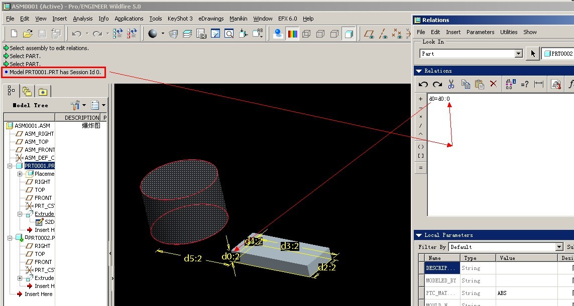
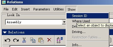
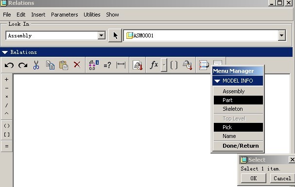
You can do that using Session ID.
First define a parameter in the assembly called for example ASM_PARAM.
Then the syntax for assembly relation to share this assembly parameter with the part would be:
PART_PARAM:SID=ASM_PARAM
A small warning. I don't know of any simple way how to find out Session ID of a part in an assembly, and I've read elsewhere that the Session ID could easily change it's value next time you load the assembly, but I can't say that's for sure.
EDIT: Lower at this post is reply from Chen that shows how to find out SID. Looks like he was faster than me.
Regards,
~Jakub
- Mark as New
- Bookmark
- Subscribe
- Mute
- Subscribe to RSS Feed
- Permalink
- Notify Moderator
Thank you for your reply Antonius, i understand the concept of top down design, i am already doing all that you describe in your reply, copying geometry from one part to another, the use of relations to control features in multiple parts, all of it.
What i was asking you for, was an explaination of how 2 parts can have a common parameter, you said "i could see a way, if both parts were in the same assembly", well they are. What i want to know is how to add a common parameter to 2 parts. I just re-read all the posts & Jayanta seems to be suggesting this can be done if you have a common assembly, well i do, so that's the question, how do you do it?
Kind Regards
John
Hello John...
I read these two as being the same thing if in the 1st statement you mean that, use a relation from one part to drive the second. Or maybe I am missing the meaning of Parameter.
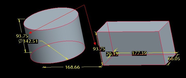
As Chenwei points out, in the assembly, the <relation>:fid_xx statement for a dimension is a relation driven from another part. I will have to set up an example or find one to clearly explain it. I usually avoid driving these things from the background. I just edit the dimension to accept the relation whenever I can.
Again, the power of Pro/E comes from being able to have features driven from part to part at the assembly level. That means you can change one feature in one component and the other components will also be altered accordingly based on this change. Say you move the spacing between two holes on one part, and the second part follows.
The other way that is being described is to set parameters in the assembly and using the parameters to drive dimensions in the sub-components. I find this more cumbersome but it is essentially the same thing with the extra step of declaring the variable. This is what Jakub is describing.
- Mark as New
- Bookmark
- Subscribe
- Mute
- Subscribe to RSS Feed
- Permalink
- Notify Moderator
For further clarification...the declaration muct be done from the part. The parameters in the notebook are then available to choose from in all parts that are declared to the notebook.
- Mark as New
- Bookmark
- Subscribe
- Mute
- Subscribe to RSS Feed
- Permalink
- Notify Moderator
Perhaps you mean:
parameter_name:fid_N or parameter_name:fid_feature_name


