1-Visitor
February 7, 2013
Solved

Sheet Metal unbend (eccentric) cone with markups

  • February 7, 2013
  • 1 reply
  • 22262 views

Hi,

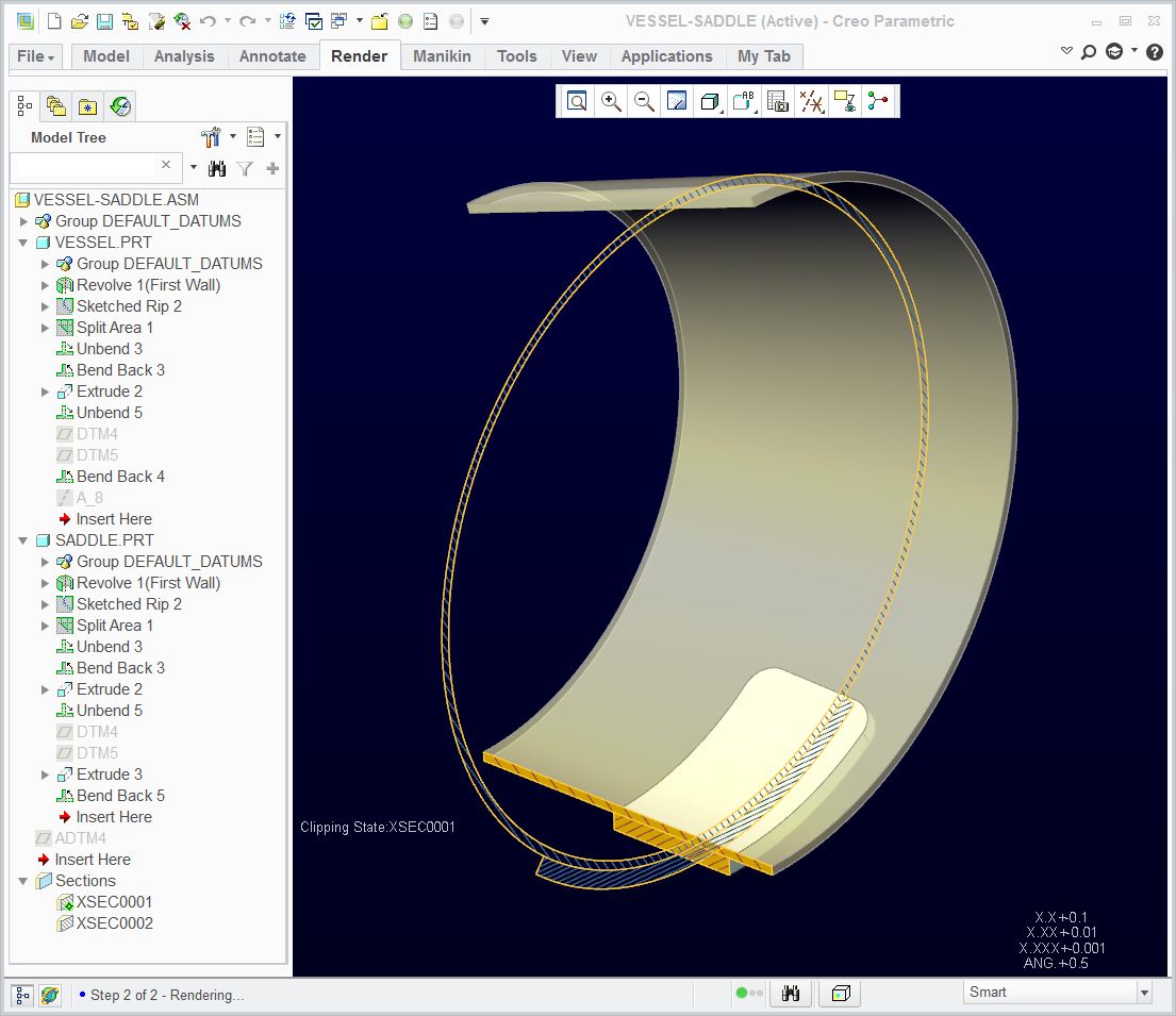
I have drawn an eccentric cone part, that I can unbend without any problems.

But, if we would like to make this part ourself, we need some markups on the flat pattern. (bend lines that show where to place our press to bend the part)

I need to define the lines/markups/... in the bended situation. They need to be transferred to the flat pattern correctly.

We need these markups for almost every sheetmetal part we want to make.

Does anyone know how to do this?

We are switching to Creo (version 2.0 M030) at this moment, we used autocad until now.

thanks a lot,

Jeroen.


This thread is inactive and closed by the PTC Community Management Team. If you would like to provide a reply and re-open this thread, please notify the moderator and reference the thread. You may also use "Start a topic" button to ask a new question. Please be sure to include what version of the PTC product you are using so another community member knowledgeable about your version may be able to assist.
Best answer by TomD.inPDX

As long as I aligned the default datums between the two part, it all lined up perfectly. If I aligned the datums created in the flat state, things shifted. Funny how that happens! Anyway, see attached Creo 2.0 files to see how this was accomplished:

Vessel-Saddle.JPG

1 reply

17-Peridot
February 7, 2013

You will have to create the bends individually in the part arranged as you envision them being formed by the tools. Doing this will provide the flat pattern with the bend information for the shop.

Jeroen1-VisitorAuthor
1-Visitor
February 11, 2013

Creating the bends individually isn't an option for us...

In this particular case, where we try to approach a perfect cone by bending the plate in X steps (for example every 5°), you are correct in theory. But I think it is not usefull to draw this eccentric cone in many individual bends because our bending will result in a nice eccentric cone, not a plate with 20 bends.

Another thing we really need, and this is pretty much the same issue:

We produce large vessels. The cylindrical parts have cut outs for nozzles. These openings are nicely unfolded and positionned on the flat state. But we also make markings on the plate. These markings are defined in the folded state, in the 3D model. These markings are needed to position internals, externals, references, ...

It is ease to place a datum point or a datum CSYS or whatever on the correct place. But these points/CSYS/ ... need to be visible on the flat state on the correct position. While lasercutting these plates, we also create these markings at the same time.

This issue is the same problem as for the eccentric cone: we need to transfer some 3D-information/positions to the 2D flat state (points, lines, CSYS, ...).

17-Peridot
February 11, 2013

Now I understand better. You should be able to make the part by forming it in the shape you want. You can unbent it and add the features you want to laser onto the faces. And then you can bend back the form to get the end result. For the drawing you can use the unbent state. In most cases, you can use relations to control exact positioning on the flat form. It is your choice as to what types of features you want to use for the laser etching, but my recommendations might be to make them shallow extrudes.

Alternatively, the markings could be done with a decal. You can apply the decal parametrically and you can use it in the drawing, but you will still need features to dimension to.

You really can make those 5 degree bends fairly smooth in Creo. Is the fabricator using dies with varying bend radii (conical) along the length? I don't know that Creo will do this with sheetmetal. For something like that I would go back to core modeling. It wouldn't be the 1st time I've had to use two models to define a product; one in the flat and on "rolled out" (rather than unfolded) when it comes to intricate cylindrical machining requirements.