Community Tip - If community subscription notifications are filling up your inbox you can set up a daily digest and get all your notifications in a single email. X
- Community
- Creo+ and Creo Parametric
- 3D Part & Assembly Design
- Re: Sheet metal - k_factor
- Subscribe to RSS Feed
- Mark Topic as New
- Mark Topic as Read
- Float this Topic for Current User
- Bookmark
- Subscribe
- Mute
- Printer Friendly Page
Sheet metal - k_factor
- Mark as New
- Bookmark
- Subscribe
- Mute
- Subscribe to RSS Feed
- Permalink
- Notify Moderator
Sheet metal - k_factor
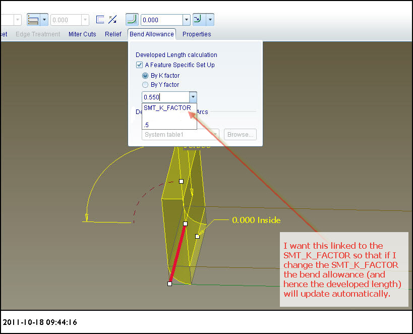
Does anyone know how I can write a relationship that will connect the bend allowance of a bend to the system parameter "SMT_K_FACTOR"? I can edit the definition of the bend and set the bend allowance to the SMT_K_FACTOR but it is not parametric, it is a one-time deal. If the change the SMT_K_FACTOR the bend does not update and I have to go in and edit the definition again.

This thread is inactive and closed by the PTC Community Management Team. If you would like to provide a reply and re-open this thread, please notify the moderator and reference the thread. You may also use "Start a topic" button to ask a new question. Please be sure to include what version of the PTC product you are using so another community member knowledgeable about your version may be able to assist.
- Mark as New
- Bookmark
- Subscribe
- Mute
- Subscribe to RSS Feed
- Permalink
- Notify Moderator
I'm doing this because we are trying to work out a bend allowance for acrylic sheet. If I use the standard bend allowance in a sheet metal part the flat pattern is too small for the bent part.
- Mark as New
- Bookmark
- Subscribe
- Mute
- Subscribe to RSS Feed
- Permalink
- Notify Moderator
Hi Graham,
I could be wrong for the latest CREO 1.0 but till now I have never able to directly access that SMT_K_FACTOR system parameter with Relations. Great pity and something I argue for in the Sheetmetal TC. Long ago I wanted to have more than one K factor used in a familty table for a part.
The traditional way to do this is to use Bend Tables. If you have a look at the Help you should get enough to set up bend values for Acrylic based on your measurements.
Hope this helps.
Regards, Brent Drysdale
- Mark as New
- Bookmark
- Subscribe
- Mute
- Subscribe to RSS Feed
- Permalink
- Notify Moderator
Hi Graham,
I`m interested how do you perform bending of acrylic phisicaly, machine or by hand. We aproximate K and radius of bend based on expirence. Hand bending can only be aproximated because of deformations in bend zone, especialy at the ends of bend line(at the sides of sheet).
- Mark as New
- Bookmark
- Subscribe
- Mute
- Subscribe to RSS Feed
- Permalink
- Notify Moderator
Davor: Yes, we bend it by hand, so its accuracy is not on par with a real sheet metal production bend. The thing that makes it much different is that we actually rout a triangular cut through the inside of the bend line and bend around this. The resulting bent form looks like a zero bend radius on the inside. We don't expect really high level of accuracy, and in fact many times it doesn't matter at all. We started this investigation when we realized that a graphic panel we were intending to stick on a bent sheet of acrylic was a good millimeter too long for the surface it was meant to go on.
Brent: I have found that the K factor, found at #Edit #Setup #Bend Allow #K-Factor can be set differently to the system parameter SMT_K_FACTOR. If I set the flange wall developed length (DEV.L) to "return to driven", then it can update automatically according to whatever change I make to the K-Factor under Edit/Setup. This is kind of what I was hoping to achieve. Unfortunately with bending acrylic this way, I will need to have different bend allowances for different angles, it's just the way it works when you are routing a groove thru the inside of the bend.
If I have a part with say, two 90 degree bends and one 60 degree bend, then the 60 degree bend will have to have a bend allowance different to the other two bends. I don't know much about bend tables, but I imagine it's not possible for a bend table to take account of this?
- Mark as New
- Bookmark
- Subscribe
- Mute
- Subscribe to RSS Feed
- Permalink
- Notify Moderator
You must use bend tables. In my company we have bend tables for each material we use (aluminium, steel, copper....) We have defined for each material and for each thickness a bend allowance.
In fact, you have to affect a bend table to the material you use.
In the bend table (2 entrie table : thickness and radius), you have to write the bend allowance. The radius is linked to the tools you use to bend the part.
Here's a screenshot of one of my bend table.
Once you have set all this, it's really cool, you just have to set the material, and bend radius, and the flat is automaticaly calculated.
Hope this helps.


