Community Tip - Did you get an answer that solved your problem? Please mark it as an Accepted Solution so others with the same problem can find the answer easily. X
- Community
- Creo+ and Creo Parametric
- 3D Part & Assembly Design
- Re: Sheetmetal multiple planars and simplified rep...
- Subscribe to RSS Feed
- Mark Topic as New
- Mark Topic as Read
- Float this Topic for Current User
- Bookmark
- Subscribe
- Mute
- Printer Friendly Page
Sheetmetal multiple planars and simplified reps
- Mark as New
- Bookmark
- Subscribe
- Mute
- Subscribe to RSS Feed
- Permalink
- Notify Moderator
Sheetmetal multiple planars and simplified reps
Working in the sheetmetal tool, I've found that you can have multiple planars, representing multiple piece parts that would be created by manufacturing, assembled into and then delivered as one part having one part number. These separate templates ( 1 of 3, 2 of 3 and 3 of 3) would all be put on the same sheet of the drawing. This is how our manufacturing has handled drawings in the past and how they and the installation crew prefer it.
Each planar is defined to its own unique datum plane which is driven off of copy geometry. I am using a unbend and bendback, one each with each planar (3 planars, 3 unbend/bendback). When I create each new unbend, it requires me to choose a planar and then select each bend individually, but no issues there - works as expected. The unbends work automatically.
I am also using a family table with the unbends suppressed/turned off in the only instance, giving me a flat state of the model. This flat instance is what I'm using to generate my drawing.
I am trying to create some simplified reps in the generic that carry over to the instance and then can be used in the drawing but am running into some issues. I am able to create a simp rep of the first planar with everything below its unbend excluded. Works beautifully. The problem is when I attempt to exclude the first planar and all associated flats and include anything beyond that. It seems everything is tied to that first set of planar/flats and if it's excluded everything else below it is too, no options. Therefor, I can't get simp reps of just the second planar/flats or the third, which is what I need for the three separate views that will go on the drawing.
In the past, we've used IDEAS or using Creo, at some point in the modeling process, converted to a sketch to generate the drawing but this breaks the association that I'm trying to keep.
So, bottom line: how do create simp reps of certain planars and associated flats while having multiple sets of planar/flats in the same sheetmetal.prt?
- Mark as New
- Bookmark
- Subscribe
- Mute
- Subscribe to RSS Feed
- Permalink
- Notify Moderator
In general, Creo Parametric does not create multi-body parts. Are you saying you are creating multiple parts bent with the same flat pattern?
- Mark as New
- Bookmark
- Subscribe
- Mute
- Subscribe to RSS Feed
- Permalink
- Notify Moderator
I'm using combinations of a unbend and bendback instead of the flat pattern. The bendbacks are turned off in the flat instance via family table. I have multiple planars/parts and each has its own unbend and bendback.
go raiders
- Mark as New
- Bookmark
- Subscribe
- Mute
- Subscribe to RSS Feed
- Permalink
- Notify Moderator
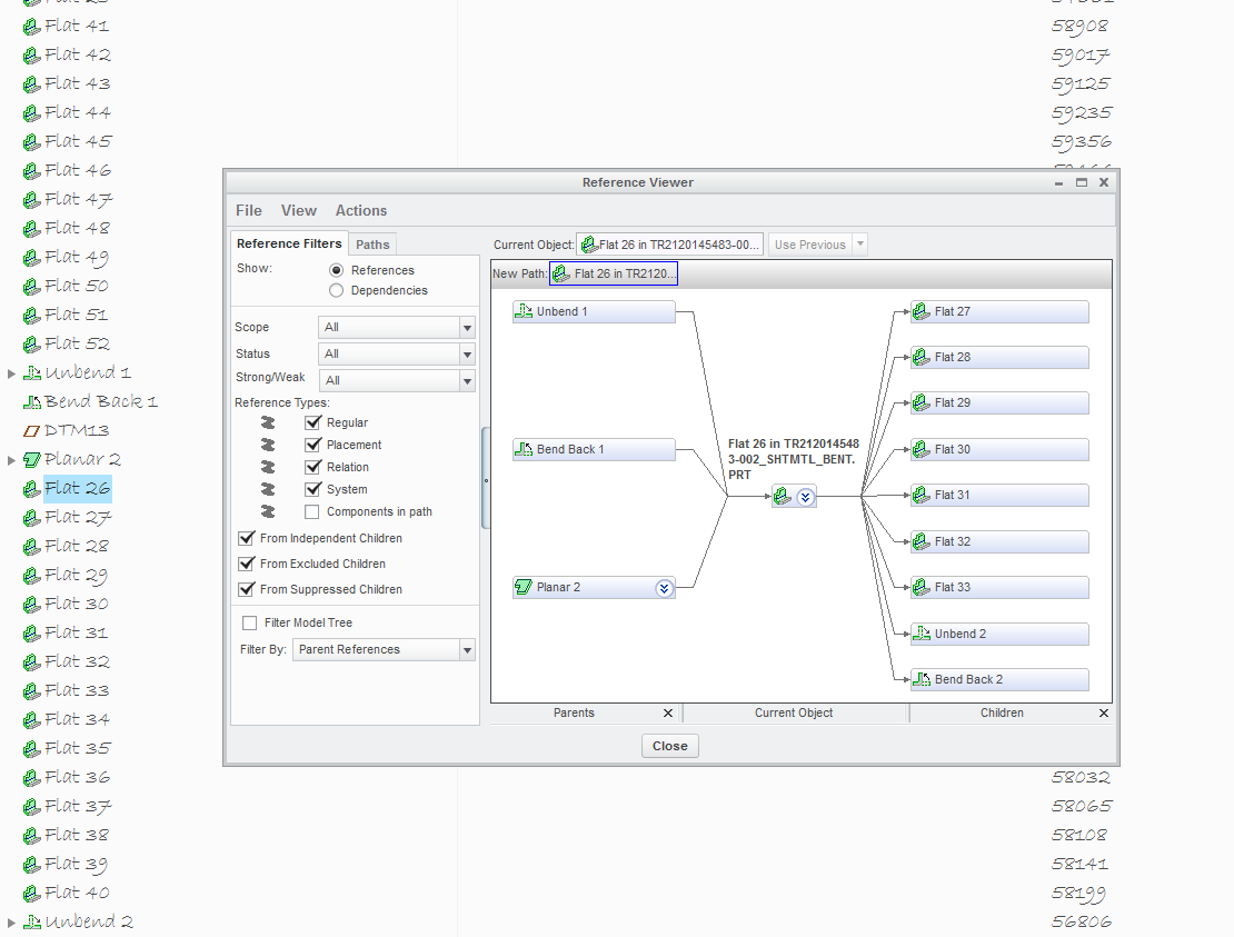
Looking at the relationship viewer, there are no relationships b/n the second and third planar and anything in the first set, but the first flat associated to the second planar has a relationship to the first unbend. The first flat associated to the third planar has a relationship to the first unbend and the first bend back.
If I suppress the first unbend and bend back, the relationship goes away and the flats that were showing the relationships don't break. If I exclude the first planar and/or unbend and bend back, everything in the second and third set is excluded automatically.
- Mark as New
- Bookmark
- Subscribe
- Mute
- Subscribe to RSS Feed
- Permalink
- Notify Moderator
correction: reference viewer
- Mark as New
- Bookmark
- Subscribe
- Mute
- Subscribe to RSS Feed
- Permalink
- Notify Moderator

- Mark as New
- Bookmark
- Subscribe
- Mute
- Subscribe to RSS Feed
- Permalink
- Notify Moderator
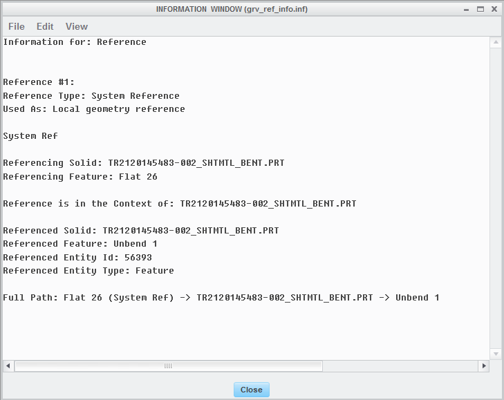
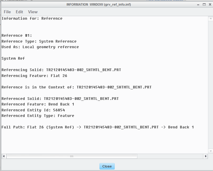
Detail on the two references, respectively:


- Mark as New
- Bookmark
- Subscribe
- Mute
- Subscribe to RSS Feed
- Permalink
- Notify Moderator
I'm thinking that when you create the first one, that determines the thickness. All the other parts reference the first one's thickness.
- Mark as New
- Bookmark
- Subscribe
- Mute
- Subscribe to RSS Feed
- Permalink
- Notify Moderator
Good point. Now that you mention it, the consecutive planars did already have their thickness set. I think there's not even an option to override and specify it. Interesting, considering there are no relationships listed in the reference viewer b/n the consecutive planars and anything in the first set since that's where the thickness is specified. The relationships are b/n flats and the first bend and bend back
- Mark as New
- Bookmark
- Subscribe
- Mute
- Subscribe to RSS Feed
- Permalink
- Notify Moderator
Are you creating multiple disjoint solid items within a single sheet metal part? If so, these are not separate parts, just separate geometry, so all the fragments are based on the same sheet metal material and thickness and every other aspect of the part definition. These characteristics are based on the first sheet metal feature, so eliminating that should have odd results.
- Mark as New
- Bookmark
- Subscribe
- Mute
- Subscribe to RSS Feed
- Permalink
- Notify Moderator
multiple, disjointed solid items within the same sheet metal part, correct. up until the simp reps, they have behaved in a manner that has been beneficial to what I need to do (I'm reluctant to state "behaved as expected" because I'm not sure exactly how they're supposed to behave). As I stated before, oddly, nothing after the first unbend and bend back has a relationship to the first planar. The second and third planar show no relationships to anything. Is is only the flats after the second and third planar that show relationships to the first unbend and/or bend back.
The only dependence I can think of is the material thickness, which it does not allow me to specify for the second and third planar - it defaults to what the first one is specified. Not sure if there's a way to override that - perhaps breaking whatever relationship there is??
- Mark as New
- Bookmark
- Subscribe
- Mute
- Subscribe to RSS Feed
- Permalink
- Notify Moderator
It would be highly unlikely to be able to break that (or those) relationships. Sheet metal is supposed to be one constant thickness. Since a "part" in Creo is one thing, the developers would have never of had a reason to give that ability to a user. If you figure out a way, there would likely be other consequences.
IDEAS was specifically designed for multi-body parts so you would anticipate it would give you options for full control over different parts within the "part"
- Mark as New
- Bookmark
- Subscribe
- Mute
- Subscribe to RSS Feed
- Permalink
- Notify Moderator
"
Stephen Williams Mar 20, 2017 10:29 AM (in response to Rob Pettigrew)
It would be highly unlikely to be able to break that (or those) relationships"
That's what I was afraid of. We are using the sheet metal tool to model fabric and metal wire mesh objects. It was specified to us from PTC via a working group with them that this was the best option they could offer. Too bad that can't offer the freedom to independently manipulate separate planars in the same sheet metal tool as far as simp reps are concerned to facilitate this.
- Mark as New
- Bookmark
- Subscribe
- Mute
- Subscribe to RSS Feed
- Permalink
- Notify Moderator
Maybe if you gave us a little more info on the product, we could possibly give you some potential solutions?
- Mark as New
- Bookmark
- Subscribe
- Mute
- Subscribe to RSS Feed
- Permalink
- Notify Moderator
PTC's parametric CAD has always been best understood as a 1:1 match with the actual manufacturing process and not a synthetic simplification for paperwork convenience.
If multiple real parts are joined they need to be modeled as independent part files assembled within an assembly file, just like what happens on the factory floor.
There is no 'relationship' to get the material thickness; that is a property of the part file, not the features in it. The thickness is set for convenience during the creation of the first feature, but maybe it shouldn't be. That would make it harder for all other users, but would make it clear that it's not feature related, any more than the material or density is.
Simplified reps were originally created to lower memory requirements; their subsequent use for configuration control is often a poor fit.
- Mark as New
- Bookmark
- Subscribe
- Mute
- Subscribe to RSS Feed
- Permalink
- Notify Moderator
And I agree completely with David,
1. In Creo, assemblies have to be used for multiple parts.
2.Simplified reps are always a bad idea to manage part or assembly configurations.
- Mark as New
- Bookmark
- Subscribe
- Mute
- Subscribe to RSS Feed
- Permalink
- Notify Moderator
Except when you have to pierce or punch and assembly because you can't add material to an assembly.
- Mark as New
- Bookmark
- Subscribe
- Mute
- Subscribe to RSS Feed
- Permalink
- Notify Moderator
Don't be saying 'except' when I didn't leave one - ![]() . It's a long standing problem that PTC fails to have material displacements (which don't add material) and additions that are common in assembly fabrication - failing to include weld material is an especially glaring example, but also potting and paint as well as the pierce/upset operations.
. It's a long standing problem that PTC fails to have material displacements (which don't add material) and additions that are common in assembly fabrication - failing to include weld material is an especially glaring example, but also potting and paint as well as the pierce/upset operations.
This is different from creating anonymous parts within a part as a factory floor preference (how do they track if one part of a set is damaged and only that item needs to be replaced?)


