Community Tip - Need to share some code when posting a question or reply? Make sure to use the "Insert code sample" menu option. Learn more! X
- Community
- Creo+ and Creo Parametric
- 3D Part & Assembly Design
- Re: Sketch to drawing
- Subscribe to RSS Feed
- Mark Topic as New
- Mark Topic as Read
- Float this Topic for Current User
- Bookmark
- Subscribe
- Mute
- Printer Friendly Page
Sketch to drawing
- Mark as New
- Bookmark
- Subscribe
- Mute
- Subscribe to RSS Feed
- Permalink
- Notify Moderator
Sketch to drawing
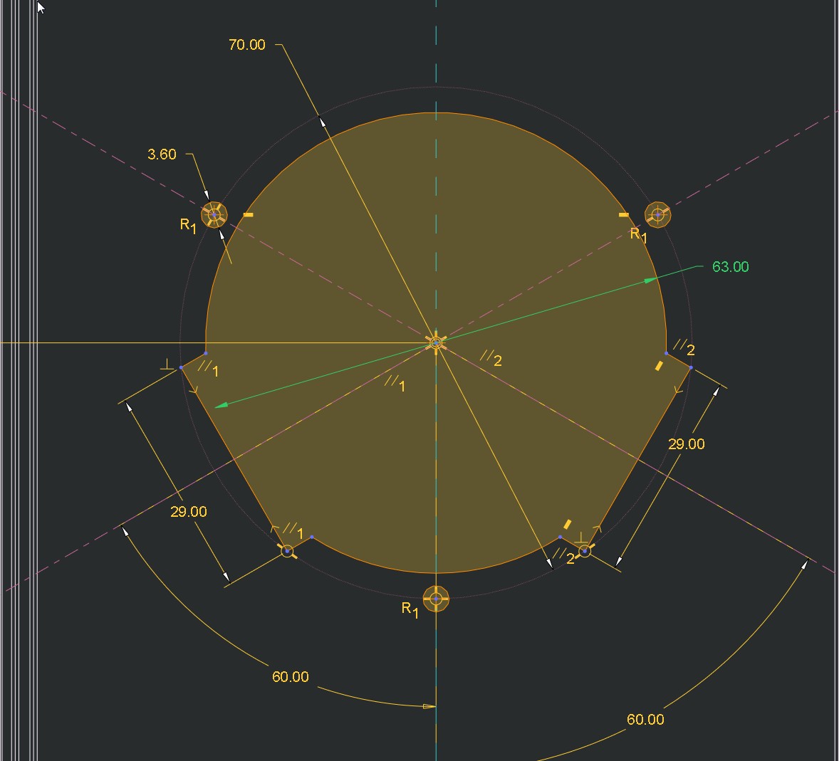
I have made a cut in the model, see image.
In the drawing I would like to use the construction circle diameter 70 to show where the 3 small holes are located.
I would also like to show the mid axis of the 29 dimension.
Can someone tell me how to do?


This thread is inactive and closed by the PTC Community Management Team. If you would like to provide a reply and re-open this thread, please notify the moderator and reference the thread. You may also use "Start a topic" button to ask a new question. Please be sure to include what version of the PTC product you are using so another community member knowledgeable about your version may be able to assist.
Solved! Go to Solution.
- Labels:
-
2D Drawing
Accepted Solutions
- Mark as New
- Bookmark
- Subscribe
- Mute
- Subscribe to RSS Feed
- Permalink
- Notify Moderator
Never sketch in drawing!
The most of simple way of showing dimensions in drawing is to add Geometry points in model sketch, and then add dimensions by measuring these points in drawing. These dimension are from model and will never broken (purple color). you can hide these points if you like clean views.
- Mark as New
- Bookmark
- Subscribe
- Mute
- Subscribe to RSS Feed
- Permalink
- Notify Moderator
You can make draft datum or axis in the drawing by drawing references from model from the annotation tab. also you can add construction circle or entity etc from the sketch tab and try relate to view so the it keeps moving with the related views.
- Mark as New
- Bookmark
- Subscribe
- Mute
- Subscribe to RSS Feed
- Permalink
- Notify Moderator
I´m quite new to this, moving from SolidWorks.
Can you be a little more clear, cause I do not see how you mean..
- Mark as New
- Bookmark
- Subscribe
- Mute
- Subscribe to RSS Feed
- Permalink
- Notify Moderator
Generaly:
1) Drawing SHOWS information from MODEL ---> all information must be included in model.
2) Make some adding sketches in drawing is WAY TO HELL.
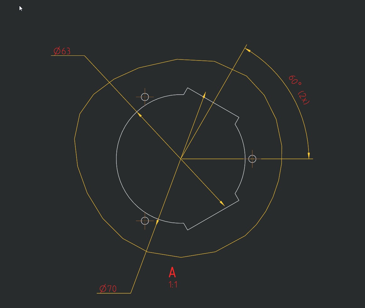
See attached pictures:
Model space:
Drawing space:
"CALL" dimmensions/axes from model.
- Mark as New
- Bookmark
- Subscribe
- Mute
- Subscribe to RSS Feed
- Permalink
- Notify Moderator
Yes, I have understood that possibilities in drawing mode are very limited compared to SolidWorks.
So still do not see how to make sketch segments visible in drawing.
Diameter 70 in my images.
- Mark as New
- Bookmark
- Subscribe
- Mute
- Subscribe to RSS Feed
- Permalink
- Notify Moderator
As far as I know you cannot make elements from a sketch that is used to create geometry visible in the drawing.
What I sometimes do is to create a separate sketch in the model, that references the geometry or the original sketch, showing only the lines I require on the drawing. I then create a new layer just for this sketch, so that I can hide it in all views except where I want it to appear.
For holes on a pitch circle, however, if you create the first hole and then axis-pattern it to create the others, it should be possible to show the correct axis and pitch circle elements automatically.
I agree with Vojtech that sketches in the drawing are always best avoided - generally they lose their parametric references and become detached from the geometry.
- Mark as New
- Bookmark
- Subscribe
- Mute
- Subscribe to RSS Feed
- Permalink
- Notify Moderator
Ok, thank you for your answer.
For me it is not a straight forward way to create a sketch, add to layer, hide layer.
I guess it will take a while for a SolidWorks user to learn how to goaround all drawing limitations.![]()
- Mark as New
- Bookmark
- Subscribe
- Mute
- Subscribe to RSS Feed
- Permalink
- Notify Moderator
Indeed - I agree!
In Part mode, the Sketcher is really good. In the Drawing, the 'sketching' tools are very bad. It's a shame.
- Mark as New
- Bookmark
- Subscribe
- Mute
- Subscribe to RSS Feed
- Permalink
- Notify Moderator
In your drawing options you need to set the radial_pattern_axis_circle option to yes.
To open the drawing options in Creo 2 selec File / Prepare / Drawing Properties. Then on the "Drawing Properties" dialog box select "Change" on the Detail Options line.
- Mark as New
- Bookmark
- Subscribe
- Mute
- Subscribe to RSS Feed
- Permalink
- Notify Moderator
Never sketch in drawing!
The most of simple way of showing dimensions in drawing is to add Geometry points in model sketch, and then add dimensions by measuring these points in drawing. These dimension are from model and will never broken (purple color). you can hide these points if you like clean views.
- Mark as New
- Bookmark
- Subscribe
- Mute
- Subscribe to RSS Feed
- Permalink
- Notify Moderator
For your paticular request, you want to change the hole axis to show the bolt circle axis.
Then you can extend the two you are concerned with through the 29.0 features.
Set this in your detail.dtl file (drawing options, not config.pro)
radial_pattern_axis_circle YES
You will have to pattern the hole features to make this work for you.


