
Turn on suggestions
Auto-suggest helps you quickly narrow down your search results by suggesting possible matches as you type.
Showing results for
Please log in to access translation
Turn on suggestions
Auto-suggest helps you quickly narrow down your search results by suggesting possible matches as you type.
Showing results for
Community Tip - Have a PTC product question you need answered fast? Chances are someone has asked it before. Learn about the community search. X
- Community
- Creo+ and Creo Parametric
- 3D Part & Assembly Design
- Re: Solidify/Cut issue in Creo Simulate containing...
Translate the entire conversation x
Please log in to access translation
Options
- Subscribe to RSS Feed
- Mark Topic as New
- Mark Topic as Read
- Float this Topic for Current User
- Bookmark
- Subscribe
- Mute
- Printer Friendly Page
Solidify/Cut issue in Creo Simulate containing an assembly with pattern
Dec 07, 2016
08:24 AM
- Mark as New
- Bookmark
- Subscribe
- Mute
- Subscribe to RSS Feed
- Permalink
- Notify Moderator
Please log in to access translation
Dec 07, 2016
08:24 AM
Solidify/Cut issue in Creo Simulate containing an assembly with pattern
Hello all
I “suspect” that the command Solidify or Cut is not behaving in well in an assembly containing pattern inside Creo / Creo simulate. So far there is no explicit restriction when using it.
As we know solidify/cut is very useful to explore symmetry in FEM to reduce computing time. Especially in Creo solidify is a good approach if your model contains components having volumes regions to be used inside the simulation. From my experience it is easy to “lose” these volumes made in the CAD parts when you have an assembly that was cut using extrude/revolve feature – but this is another case…
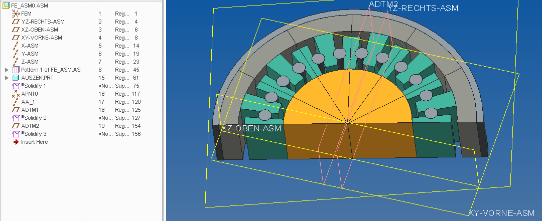
The below assembly (4 CAD parts) was also made patterning some sub-components.
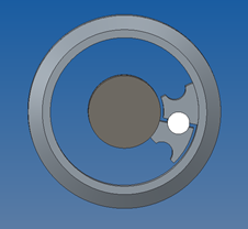

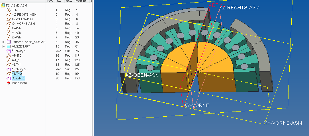
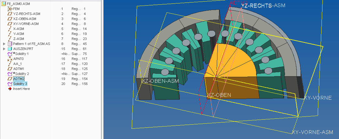
When I try to simplify it using the feature "solidify" (fig. a) the result is bad. If instead I create a volume to cut half of the assembly (fig. b) the result looks god – but not once the model is inside Cre Simulate (fig. c, d)!
a b
b 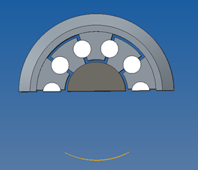
c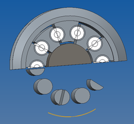 d
d 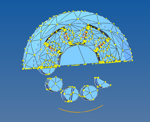
I do not see any logic or restriction why these commands should not work well with pattern. One can argue that since the model contains pattern we can pattern just enough to create the symmetry. This is indeed what I think I have to do in this case but truly it is not the best way since you have to build the model again – what can be very time demand in some cases.
_Has someone faced such problem and found a solution or work around?? I´m using Creo 2.0 M150.
Thanks,
R. Rabe
This thread is inactive and closed by the PTC Community Management Team. If you would like to provide a reply and re-open this thread, please notify the moderator and reference the thread. You may also use "Start a topic" button to ask a new question. Please be sure to include what version of the PTC product you are using so another community member knowledgeable about your version may be able to assist.
Labels:
- Labels:
-
Assembly Design
9 REPLIES 9
Dec 07, 2016
09:18 AM
- Mark as New
- Bookmark
- Subscribe
- Mute
- Subscribe to RSS Feed
- Permalink
- Notify Moderator
Please log in to access translation
Dec 07, 2016
08:06 PM
- Mark as New
- Bookmark
- Subscribe
- Mute
- Subscribe to RSS Feed
- Permalink
- Notify Moderator
Please log in to access translation
Dec 07, 2016
08:06 PM
This really is a problem that I met before. The solidify functionality sometimes doesn't work. You can use extrude-remove material to cut what you don't need. Maybe this is a workaround.
Dec 08, 2016
04:28 AM
- Mark as New
- Bookmark
- Subscribe
- Mute
- Subscribe to RSS Feed
- Permalink
- Notify Moderator
Please log in to access translation
Dec 08, 2016
04:28 AM
Thanks for confirming the issue
In my example the extrude cut "worked" in the CAD environment (fig b) but once in Simulate the assembly came degenerated having some cylinders included (fig c) - consequently this was not a solution.
However Paul just sent another assembly that suffers the same problem when using the function "solidify" but on the other hand a "extrude cut" shows the same model in CAD and in Simulate. In this case "cut" worked well.
My conclusion was that the way as the assembly is made seems to have an influence - although it is difficult to determine what will work.
Since this is a problem the best way is to plan in advance the FEM model and try to avoid to make use of symmetry by cutting the model in an assembly with pattern.
Ps: A bit off topic:
I found that if you have created a FEM volumes region in your part and after “cut” it in an assembly it is possible that you lose these FEM volume in your assembly. I noticed that this issue happens more often if you have created these volume regions in your part not using standard drawing shapes but yet making use of “offset “or “project” for example.
In the same way it is a very good practice to create any volumes (in a part or assembly) before to cut the part/assembly.
Dec 08, 2016
05:47 AM
- Mark as New
- Bookmark
- Subscribe
- Mute
- Subscribe to RSS Feed
- Permalink
- Notify Moderator
Please log in to access translation
Dec 08, 2016
05:47 AM
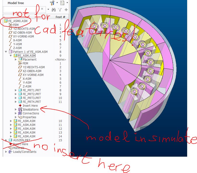
model in simulate is not the same cad-model.
(example in creo simulate 2.0 m08
Regards
Paul
Dec 08, 2016
02:53 PM
- Mark as New
- Bookmark
- Subscribe
- Mute
- Subscribe to RSS Feed
- Permalink
- Notify Moderator
Please log in to access translation
Dec 08, 2016
02:53 PM
The cutting plane used in a solidify feature has to intersect the geometry for it to work. At the part level you see the same thing happen when you add a plane that intersects the geometry and then drag the plane in the direction opposite that the direction arrow is pointing. More of the part is removed and when the plane no longer intersects the geometry (part is entirely on the side of the plane where material is to be removed) the entire part is displayed. Since the cutting plane doesn't intersect the geometry of the parts (shown in your picture a) in the assembly the material isn't removed.
Dec 09, 2016
04:30 AM
- Mark as New
- Bookmark
- Subscribe
- Mute
- Subscribe to RSS Feed
- Permalink
- Notify Moderator
Please log in to access translation
Dec 09, 2016
04:30 AM
Thanks Kevin
But I´m sorry to say that I could not understand how your explanation can be applied in the assembled case. Or is it basically a comment?
Just to make sure I just picked-up a datum plane of my choice and applied the command found under ”Modifiers>Solidify” in the assembly model.
From my understanding it simples “cut” the entire assemble to the left or right depending of the choice.
The problem is that or it behaves completely erratic or there are some important rules to follow – that I really don´t know.
For example here is the assembly model “fe_asm0_v2” that you can find in the message from Paul (above). I have just added two new datum planes.
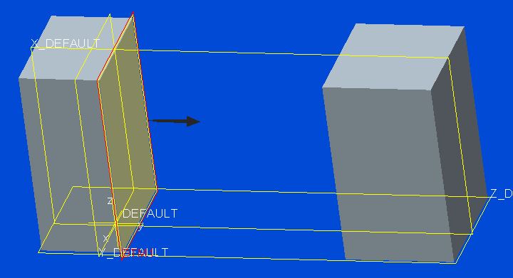
I created a diagonal plane in the height direction and the solidify result was ok in CAD and inside Simulate.

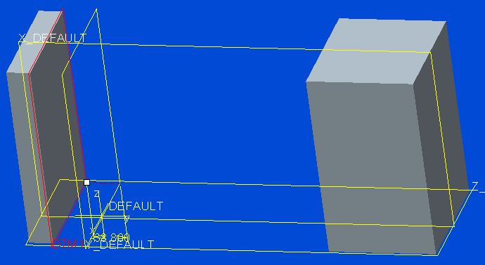
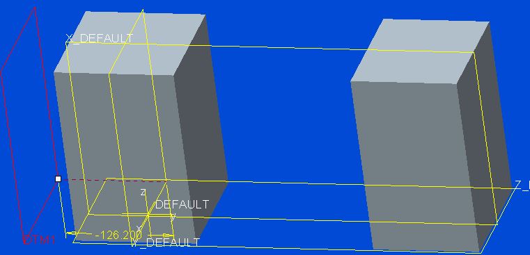
Now I just created an offset plane in the side direction. The result is bad and also completely different depending even the direction of the cut!
Indeed the best solution is to prepare the symmetric model since the beginning (a suitable CAD parts design) and not after, using cut-extrude or solidify function in the final assembly.
"Cut" and "Pattern" have relationship problems when sharing the same assembly...
Dec 09, 2016
05:31 AM
- Mark as New
- Bookmark
- Subscribe
- Mute
- Subscribe to RSS Feed
- Permalink
- Notify Moderator
Please log in to access translation
Dec 09, 2016
05:31 AM
Hi,
model in simulate (fe) is not for cad features
Regards
Paul
Dec 09, 2016
10:17 AM
- Mark as New
- Bookmark
- Subscribe
- Mute
- Subscribe to RSS Feed
- Permalink
- Notify Moderator
Please log in to access translation
Dec 09, 2016
10:17 AM
In order for a solidify feature to remove material the feature used to cut the model has to meet certain conditions it doesn't just simply remove what's to the left or right of the plane. In the case of a cutting plane (datum plane) the plane must intersect (pass through) the feature geometry or model geometry.
In your second picture it's a bit hard to tell what the cutting plane passes through but it looks like it passes through all the parts (pieces). In the third picture the orange wedges in the center, the outer ring, one of the inner grey rings, and two of the wedges between the cylinders have material removed because the cutting plane passes through the geometry, the cutting plane doesn't pass through any of the cylinders. In the fourth picture the same parts (pieces) have the opposite side of the material removed because you changed the side of material removal.
You can see the same behavior in a part. You see it by having the plane pass through the solid geometry, when you move the plane in the direction opposite to the direction the direction arrow for material removal points you should see more of the geometry gets removed from display. When the plane no longer intersects the geometry the entire part gets displayed.
You also see this behavior in a part if geometry regions are not connected. If the plane passes through only one of them, the region the plane passes through will have material removed the other will always display.
I'm not a Simulate user but from the steps I've seen used to prepare models I could see where an assembly cut might cause problems if my assumptions are correct. My assumption is Simulate would want the cut at the part level. Since you are using a pattern of a part you run into problems since you have a part in three states: no removal, partial removal, and complete removal of material. My guess, based on on what I'm seeing, is your original assembly with the hub, outer ring, cylinders and retainers would only end up with the hub and outer ring if the intersected cut was redefined to intersect at the part level.
Dec 13, 2016
05:33 AM
- Mark as New
- Bookmark
- Subscribe
- Mute
- Subscribe to RSS Feed
- Permalink
- Notify Moderator
Please log in to access translation
Dec 13, 2016
05:33 AM
The solidify/cut function in assembly belongs to the CAD and this should not have difference in the FEM environment. So what you get in CAD should be the same in FEM.
However this is not always true as I showed in the figure “b” and “c” where cutting half of the model is ok in CAD but is displaced (and meshed) wrongly in Simulate. So I believe that there is a bug here but it can be much related to how the part is model because I could get away of this problem just by modifying the original part (ex. not using project or offset a reference) – don´t ask me way.
I think you are not far away analyzing the way as Creo cuts an assembly. If you analyze the pattern after a cut in assembly you can see extra cut volumes. If In a pattern the volume is not there it means that it was not created. Why it was not created is the open point. It can indeed be that sometimes the plane can intercept “everything” but in other cases it finds an “empty” and the part is ignored.
One could think that choosing the “right plane” like selecting a plane from a part that is also patterned in the same way could overcome this problem. Unfortunately this is not the case because the result is the same.
Even if this is not a “bug” I feel that the command could be more robust with some options to force the cut. I could not find the document again but it seems that you could even set in Creo that to not include some parts when cutting an assembly. So if you can define the parts not to be cut you could also define how all the parts are cut – like a “cut up to”.
Anyway, I got enough examples in this discussion to create the right assembly and not I´m aware now that cuts in an assembly with pattern can have unexpected results.
So if you have the option, avoid it!
Taking the chance, I would like to thank you all for the contributions.


