
Turn on suggestions
Auto-suggest helps you quickly narrow down your search results by suggesting possible matches as you type.
Showing results for
Please log in to access translation
Turn on suggestions
Auto-suggest helps you quickly narrow down your search results by suggesting possible matches as you type.
Showing results for
- Community
- Creo+ and Creo Parametric
- 3D Part & Assembly Design
- Re: Spreader Beam Analysis
Translate the entire conversation x
Please log in to access translation
Options
- Subscribe to RSS Feed
- Mark Topic as New
- Mark Topic as Read
- Float this Topic for Current User
- Bookmark
- Subscribe
- Mute
- Printer Friendly Page
Spreader Beam Analysis
Jul 06, 2015
11:53 AM
- Mark as New
- Bookmark
- Subscribe
- Mute
- Subscribe to RSS Feed
- Permalink
- Notify Moderator
Please log in to access translation
Jul 06, 2015
11:53 AM
Spreader Beam Analysis
I am having trouble getting believable results from simulate while analyzing a simple spreader beam.
I am new to simulate, so I don't know if I am constraining and/or loading it correctly. Any advise would be appreciated.
The beam is very simple. It is just a piece of 1" thick plate 147" long by 12" wide with 1-3/8" holes spaced 6" apart along both long edges for rigging.
2 pieces of 2" x 4" x 1/4" rectangular tubing will be welded to the sides for torsional support. See attached picture for a visual.
For the worst case scenario, the beam is to be picked at the top center hole with the load hung from the two outer most bottom holes.
It needs to hold 25,000 lbs, but so far my results have shown that it will not. Not even close. I don't believe these results because the man who suggested the design has been rigging for decades and would build this thing and use it without a second thought. I've been messing with constraints and loads - what kind to use, how to apply them, etc. Half of my attempts fail with "not enough constraints", and the ones that succeed show outlandish stresses over very small areas around the circumference of the holes. Pin constraints and bearing loads make the most sense to me for this, but I'm just not getting results. How do you do this?
And yes, all of my material properties are in good order. 
Thanks, Luke
This thread is inactive and closed by the PTC Community Management Team. If you would like to provide a reply and re-open this thread, please notify the moderator and reference the thread. You may also use "Start a topic" button to ask a new question. Please be sure to include what version of the PTC product you are using so another community member knowledgeable about your version may be able to assist.
Solved! Go to Solution.
Labels:
- Labels:
-
Surfacing
ACCEPTED SOLUTION
Accepted Solutions
Jul 06, 2015
02:06 PM
- Mark as New
- Bookmark
- Subscribe
- Mute
- Subscribe to RSS Feed
- Permalink
- Notify Moderator
Please log in to access translation
Jul 06, 2015
02:06 PM
Lucas,
You will get high stresses around all the holes. These are all stress raisers by an unscientific factor of 3-ish.
1. Do a hand calc to get max stress in outer fibre at centre support and approx. deflection of the ends
Assume half the beam is a built in cantilever, ignore the holes.
Suppress the holes (other than those required for loads and constraints). This will show whether your FEA is in the same ball park or whether something is very wrong.
2. The section is symmetric, you could use a sketched beam section and try beam elements. This is another quick and simple way of confirming hand calc/solid model is in the correct ball park.
3. Multiply the stress at the hole outer edge distance from the neutral axis by the unscientific factor. (Peterson's is more scientific) and compare with the solid model.
The above offers confidence but not refinement.
If you have a pin constraint in the centre with the rotation DOF set as free and an equal load at each end, then your model will tip like a see-saw and fail insufficiently constrained. This is a numerical method.
I would propose you consider a 'weak' ground spring at one end. Any numerical imbalance will be carried by this spring.
Your hand calc will tell you approx. how much deflection to expect. The spring should not exert more than say 1% of the applied load in the direction of the load at that end when fully deflected.
There are other methods for another day.
Regards
13 REPLIES 13
Jul 06, 2015
01:00 PM
- Mark as New
- Bookmark
- Subscribe
- Mute
- Subscribe to RSS Feed
- Permalink
- Notify Moderator
Please log in to access translation
Jul 06, 2015
01:00 PM
After digging further into my material properties, I am concerned. I opened up the text file for my steel plate material which was created long ago and not by me. The numbers would be correct if the units were in psi. Young's modulus for example is 2.9e7. However the units are in lbm/(in sec^2). I've been looking into this unit that Creo seems to use extensively, and I do not understand it. Is it the same thing as lbf/in^2 in which case the Young's modulus would be correct? Why is it presented in this way? I'm not feeling like a very good engineer today. I need to understand this stuff. Thanks for any help!!
Jul 06, 2015
02:38 PM
- Mark as New
- Bookmark
- Subscribe
- Mute
- Subscribe to RSS Feed
- Permalink
- Notify Moderator
Please log in to access translation
Jul 06, 2015
02:38 PM
Lucas,
Create a 1x1x1 cube.
Ensure that you are conscious of your model units (know where you are).
Assign your material.
Check the mass props and the numbers/units in the material definition form.
Note, you can enter material property numbers in any unit system by the drop down lists regardless of model units.
The software will perform the appropriate conversion behind the scenes.
Make sure it makes sense.
It is possible and interesting to look at and edit the info in the .mat files. Don't. Carry out this exercise via the UI being aware of your units from the pull down lists (defaults to you model units).
Regards
Jul 07, 2015
03:46 AM
- Mark as New
- Bookmark
- Subscribe
- Mute
- Subscribe to RSS Feed
- Permalink
- Notify Moderator
Please log in to access translation
Jul 07, 2015
03:46 AM
I'm so happy we have SI units in the civilised world 
1 lbf = 1 lbm * g
so 1 lbf/(in^2) = 1 lbm g / (in^2)
and g = 32.17 ft/(s^2) = 32.17 * 12 * in/(s^2)
so 1 lbf/(in^2) = 32.17*12 lbm / (in*s^2)
Seems like your material properties are off by a factor of 386 then.
Please keep in mind that lifting equipment is subject to strict safety factors prescribed by standards.
I think in your case you need to comply with ASME BTH-1.
Jul 07, 2015
07:16 AM
- Mark as New
- Bookmark
- Subscribe
- Mute
- Subscribe to RSS Feed
- Permalink
- Notify Moderator
Please log in to access translation
Jul 07, 2015
07:16 AM
Patrick Asselman wrote:
I'm so happy we have SI units in the civilised world
Even then, we have people who insist on using mm-kg-s model units, resulting in forces in mN, torques in u-Nm and stresses in kPa (I think!)...
Jul 08, 2015
03:35 AM
- Mark as New
- Bookmark
- Subscribe
- Mute
- Subscribe to RSS Feed
- Permalink
- Notify Moderator
Please log in to access translation
Jul 08, 2015
03:35 AM
True, and that is difficult enough without the extra complexity of a factor of g expressed in in/s^2 and other stuff like that!
Jul 07, 2015
12:41 PM
- Mark as New
- Bookmark
- Subscribe
- Mute
- Subscribe to RSS Feed
- Permalink
- Notify Moderator
Please log in to access translation
Jul 07, 2015
12:41 PM
Thank you Patrick. That does make more sense now, although I was taught that 1 lbm = 1 lbf on Earth. I understand what Creo is doing by expressing pressure units in this way, but I sure don't know why. Is there any practical use for the lbm/(in*sec^2) unit?
And you were correct about the factor of 386. I was able to verify a hand calc for deflection on a very simplified model in Creo once I changed all the stress/strain properties to psi in the material properties. Apparently, whoever created our material files years ago just plugged in properties with no regard for the units. It's never been a problem because we typically don't do stress analysis in Creo.
Thanks, Luke
Jul 08, 2015
03:50 AM
- Mark as New
- Bookmark
- Subscribe
- Mute
- Subscribe to RSS Feed
- Permalink
- Notify Moderator
Please log in to access translation
Jul 08, 2015
03:50 AM
No idea where it comes from, but I suspect it is similar to mm-kg-s. I see it used a lot here with engineers who do not need to calculate anything. It is convenient for them because they think in millimeters and kilograms, and they don't care that the resulting force is 0.001 Newtons.
Convenience often dictates the use of units. The boatsmen used furlong per fortnight, astronomers use AU's, etc.
Jul 07, 2015
05:31 AM
- Mark as New
- Bookmark
- Subscribe
- Mute
- Subscribe to RSS Feed
- Permalink
- Notify Moderator
Please log in to access translation
Jul 07, 2015
05:31 AM
Can you change the units in the Edit > Setup menu??
I know that's how I change between length units when modelling but not sure if this applies to material properties also.
Jul 06, 2015
02:06 PM
- Mark as New
- Bookmark
- Subscribe
- Mute
- Subscribe to RSS Feed
- Permalink
- Notify Moderator
Please log in to access translation
Jul 06, 2015
02:06 PM
Lucas,
You will get high stresses around all the holes. These are all stress raisers by an unscientific factor of 3-ish.
1. Do a hand calc to get max stress in outer fibre at centre support and approx. deflection of the ends
Assume half the beam is a built in cantilever, ignore the holes.
Suppress the holes (other than those required for loads and constraints). This will show whether your FEA is in the same ball park or whether something is very wrong.
2. The section is symmetric, you could use a sketched beam section and try beam elements. This is another quick and simple way of confirming hand calc/solid model is in the correct ball park.
3. Multiply the stress at the hole outer edge distance from the neutral axis by the unscientific factor. (Peterson's is more scientific) and compare with the solid model.
The above offers confidence but not refinement.
If you have a pin constraint in the centre with the rotation DOF set as free and an equal load at each end, then your model will tip like a see-saw and fail insufficiently constrained. This is a numerical method.
I would propose you consider a 'weak' ground spring at one end. Any numerical imbalance will be carried by this spring.
Your hand calc will tell you approx. how much deflection to expect. The spring should not exert more than say 1% of the applied load in the direction of the load at that end when fully deflected.
There are other methods for another day.
Regards
Jul 06, 2015
03:11 PM
- Mark as New
- Bookmark
- Subscribe
- Mute
- Subscribe to RSS Feed
- Permalink
- Notify Moderator
Please log in to access translation
Jul 06, 2015
03:11 PM
Charles,
Thank you for your reply. I've moved on to another more urgent project for the time being, but I'll be back to try your suggestions in a day or two. I might have to dig out a text book to do stress and deflection hand calcs. It's been a long time, and that was never my specific area of study.
Thanks again and I'll get back to you,
Luke
Jul 07, 2015
04:03 PM
- Mark as New
- Bookmark
- Subscribe
- Mute
- Subscribe to RSS Feed
- Permalink
- Notify Moderator
Please log in to access translation
Jul 07, 2015
04:03 PM
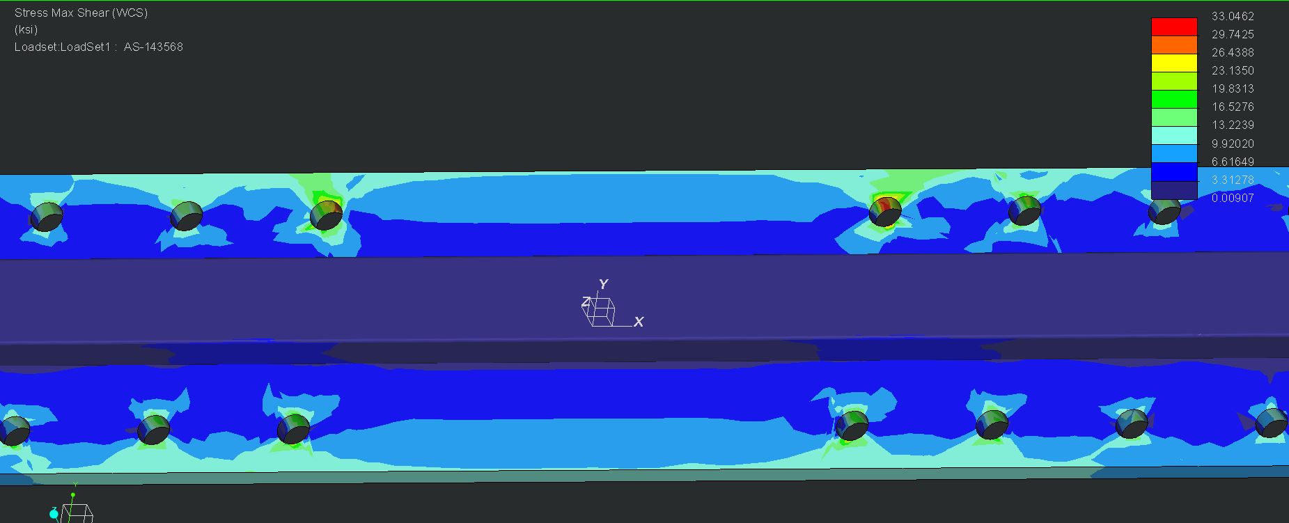
Thanks everyone for the advice. I was able to get results I'm comfortable with. I am eliminating the three center holes on top and bottom to assure that the beam is always picked in two places. This alleviates some of the shear stress on the pick points. Creo still wants to give me high stresses over small areas on the circumference of the pinned holes, but I'm not seeing the same effect on the load bearing holes, and my hand calcs are giving the holes more than enough safety factor. If anyone has experience with designing rigging, I'd love to know if you see the same thing, or if you have a preferred way to constrain a free hanging spreader beam such as this.
Thanks, Luke
Jul 08, 2015
03:34 AM
- Mark as New
- Bookmark
- Subscribe
- Mute
- Subscribe to RSS Feed
- Permalink
- Notify Moderator
Please log in to access translation
Jul 08, 2015
03:34 AM
Stresses always tend to get high near constrained points or areas.
What you can do in this case is do one analysis with constraints on the top holes and bearing forces on the bottom holes, and then do a second analysis with the constraints on the bottom holes and the bearing forces on the top holes.
Jul 08, 2015
07:26 AM
- Mark as New
- Bookmark
- Subscribe
- Mute
- Subscribe to RSS Feed
- Permalink
- Notify Moderator
Please log in to access translation
Jul 08, 2015
07:26 AM
I have done rigging designs similar to this. I agree with what others have said. It is standard to ignore the local effects and instead solve those interfaces with a closed form solution (ie hand calc).


