Community Tip - Did you get called away in the middle of writing a post? Don't worry you can find your unfinished post later in the Drafts section of your profile page. X
- Community
- Creo+ and Creo Parametric
- 3D Part & Assembly Design
- Re: Spur Gear and Helical Gears
- Subscribe to RSS Feed
- Mark Topic as New
- Mark Topic as Read
- Float this Topic for Current User
- Bookmark
- Subscribe
- Mute
- Printer Friendly Page
Spur Gear and Helical Gears
- Mark as New
- Bookmark
- Subscribe
- Mute
- Subscribe to RSS Feed
- Permalink
- Notify Moderator
Spur Gear and Helical Gears
Hello Guys,
I have just entered to an automobile company, and I have been posted in Transmission Design Department. So, I want to learn modelling of Spur Gears and Helical Gears. Where can I get such info for modelling gears in Creo (with all the nomenclature that we normally use while modelling a gear)?
And also can I get Gear calcualtion sheet or something that I can refer..?
This thread is inactive and closed by the PTC Community Management Team. If you would like to provide a reply and re-open this thread, please notify the moderator and reference the thread. You may also use "Start a topic" button to ask a new question. Please be sure to include what version of the PTC product you are using so another community member knowledgeable about your version may be able to assist.
- Labels:
-
Surfacing
- Mark as New
- Bookmark
- Subscribe
- Mute
- Subscribe to RSS Feed
- Permalink
- Notify Moderator
That's a big subject, Naveen.
What will you be doing with your models? Will they be passed to manufacturing? Are you doing analysis with them? Or are they simply a placeholder for getting a good model of a transmission?
Most gear manufacturers have excellent data available. Not to the level of power transmission, but at least the basics of gear design and manufacturing.
I really like the handbooks provided by SDP-SI. http://www.sdp-si.com/Catalogs.htm
They have some download models in Pro/E format that are generated on the fly. They will help but do not count on them for being "gospel".
Also be very careful if you do need precise gears. Hobs are different from Creo tools. I have not seen anything in Creo that does an accurate representation of "round" cutting tools. It makes a difference if you just sweep flat sections in many cases. For instance, the involute of a gear tooth is actually the result of the manufacturing process but we have to work hard to define it. Ground threads, for instance, also creates a different profile than one would think.
Congratulations on your new job, Naveen.
- Mark as New
- Bookmark
- Subscribe
- Mute
- Subscribe to RSS Feed
- Permalink
- Notify Moderator
As Antonius says, the intended use of your gear model is important.
For technical drawings used for getting gears fabricated, you normally do not need an accurate model as long as you specify all the needed information the fabricator needs. I.ex for paralel spur gears; Modul size, number of teeth, pressure angle, degree of accuracy and so on...
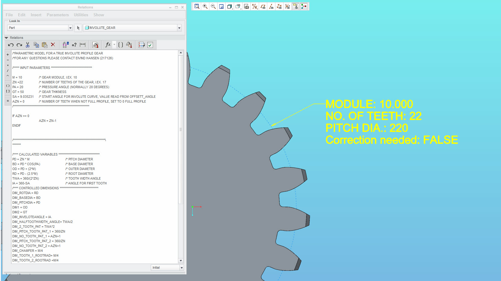
However, for good fun, I have started on making a parametric model of a straight/parallel spur gear / pinion that have a true involute tooth profile. This is based on the modul system, and for now it look quite good. I was inspired by this document: http://www.cadquest.com/books/pdf/gears.pdf
I have planes for adding correction / profile shifting to this also....

- Mark as New
- Bookmark
- Subscribe
- Mute
- Subscribe to RSS Feed
- Permalink
- Notify Moderator
You might find this interesting... pattern using rotate and distance
This was to determine the undercut for small gears but also shows a means to determine the profile in the bottom of the gear tooth based on hobbing gear teeth using a rack profile hob.

- Mark as New
- Bookmark
- Subscribe
- Mute
- Subscribe to RSS Feed
- Permalink
- Notify Moderator
This looks like a well thought out gear template. Are you willing to share this model?
- Mark as New
- Bookmark
- Subscribe
- Mute
- Subscribe to RSS Feed
- Permalink
- Notify Moderator
If you are referring to my model, sure I will share it. Just need to make a version without the corporate part-template included, as I don't think I am allowed to share that... I'll see what I can do in the following days...
- Mark as New
- Bookmark
- Subscribe
- Mute
- Subscribe to RSS Feed
- Permalink
- Notify Moderator
Yes - What looks interesting to me is the ability to enter the gear parameters and have the relations properly create the gear geometry.
- Mark as New
- Bookmark
- Subscribe
- Mute
- Subscribe to RSS Feed
- Permalink
- Notify Moderator
Hi,
I have uploaded a rev 01 of the template here: http://communities.ptc.com/docs/DOC-6295
Made in Creo 2.0 M110
THIS TEMPLATE HAS NOT BEEN FULLY CHECKED, HENCE ERRORS MAY OCCUR
***** USE AT YOUR OWN RISK *****
- CREATOR OF THIS TEMPLATE TAKES NO RESPONSIBILITY FOR ANY DAMAGE, ERROR OR ISSUES WHATSOEVER THAT MAY BE A RESULT OF THE USE OF THIS TEMPLATE
- PLEASE NOTE THAT FOR CONFIGURATIONS WHERE UNDERCUTTING OCCURS, ACTUAL UNDERCUT PROFILE IS NOT GENERATED!
IT IS ADVISABLE TO MAKE YOUR GEARS WITH NO UNDERCUT - ProProgram CODE IS USED FOR SUPPRESSING/RESUMING SOME FEATURES BASED ON INPUT PARAMETERS
For any errors or malefunctions, please let me know!
- Mark as New
- Bookmark
- Subscribe
- Mute
- Subscribe to RSS Feed
- Permalink
- Notify Moderator
As a gearbox/transmission designer, I agree with Elvind that for most purposes it's not necessary to model the teeth accurately, as the form is generated by the cutting machines, and they take the gear data in parametric form in any case. Most of our gear models just have an arc to represent the flanks - it looks good enough, is easy to model and regenerates quickly.
Gear calculation is best done by purpose-written software (such as Ricardo SABR-GEAR: http://www.ricardo.com/en-GB/What-we-do/Software/Products/SABR/Gear-design/ </shameless plug> ![]() ).
).
Having said that, there have been a few occasions where I've wanted an accurate model to run FEA on. I've found that the simplest and most flexible method for spur gears is to use an equation-driven curve to generate a single involute, which requires just the base circle diameter. You can then take the over-pins dimension to generate a sketch making the pin tangent to the flank, mirror the involute using a plane through the centre of the pin, and then use another sketch to create the root fillet tangent to the root diameter.
Having said that, this assumes that a full-fillet root is a sufficient representation (strictly speaking the root should be a trochoid); and I've yet to create a helical gear successfully - controlling the normal direction and rotation of the section correctly as it sweeps along the helix is difficult to say the least.


