
Turn on suggestions
Auto-suggest helps you quickly narrow down your search results by suggesting possible matches as you type.
Showing results for
Please log in to access translation
Turn on suggestions
Auto-suggest helps you quickly narrow down your search results by suggesting possible matches as you type.
Showing results for
Community Tip - Did you know you can set a signature that will be added to all your posts? Set it here! X
- Community
- Creo+ and Creo Parametric
- 3D Part & Assembly Design
- Re: Stress in joint through prestressed bolt
Translate the entire conversation x
Please log in to access translation
Options
- Subscribe to RSS Feed
- Mark Topic as New
- Mark Topic as Read
- Float this Topic for Current User
- Bookmark
- Subscribe
- Mute
- Printer Friendly Page
Stress in joint through prestressed bolt
Nov 19, 2014
10:57 AM
- Mark as New
- Bookmark
- Subscribe
- Mute
- Subscribe to RSS Feed
- Permalink
- Notify Moderator
Please log in to access translation
Nov 19, 2014
10:57 AM
Stress in joint through prestressed bolt
Hi,
I am using Creo 2.0, and I am interested in finding out more about the stress in a joint due to a prestressed bolt. I am using a dummy-model, consisting of two identical plates(aluminum) with 18mm holes in the middle. I am using the fastener feature and prestress my M16 bolt(steel) with 59.8kN. I use fixed separation=on and default bonded interface(no contact interfaces defined whatsoever). After the first run, Fastener1_axial_force=24kN, as I understand for the second run I must prestress 59.8*59.8/24=149kN, is this correct?
Furthermore, the stress in the joint is high, there are considerable regions where it is above 200MPa. As most aluminums have an Rp0.2 lower than this, this is a problem.
So the question is: Am I missing something? Is the Creo fastener tool a good tool to see the stresses induced in the joint?
Best
Andreas
This thread is inactive and closed by the PTC Community Management Team. If you would like to provide a reply and re-open this thread, please notify the moderator and reference the thread. You may also use "Start a topic" button to ask a new question. Please be sure to include what version of the PTC product you are using so another community member knowledgeable about your version may be able to assist.
10 REPLIES 10
Nov 19, 2014
03:09 PM
- Mark as New
- Bookmark
- Subscribe
- Mute
- Subscribe to RSS Feed
- Permalink
- Notify Moderator
Please log in to access translation
Nov 19, 2014
03:09 PM
Is the Creo fastener tool a good tool to see the stresses induced in the joint?
Generally speaking, it's not, but it really depends on the specifics of the system you're using it within. The fastener tool creates an idealization of a fastener by using several springs and linking elements, and is primarily used to give a more realistic representation of the load transfer through a structure as opposed to a bonded interface or rigid linking surfaces together. In certain situations the fastener tool can give a reasonable level of accuracy in the stresses in the neighboring material, but this assumes that you've set the fastener up correctly. The preload, fix separation, and frictionless interface can have a very large impact on the results given, so you need to be very careful and ensure that including these effects are appropriate for the nature of the joint.
All that being said, if you're really concerned with the stresses in the fastener and the neighboring material, then doing a 3D solid representation of the fastener (minus the threads in most cases) with contact interfaces is probably the best bet. However, as I said before, you might be able to use the fastening tool if the situation is appropriate for it and if you set it up correctly.
After the first run, Fastener1_axial_force=24kN, as I understand for the second run I must prestress 59.8*59.8/24=149kN, is this correct?
Yup.
I use fixed separation=on...
This is one of the setup properties that you need to be very careful with.
Furthermore, the stress in the joint is high, there are considerable regions where it is above 200MPa
Did your stresses converge?
Nov 20, 2014
11:22 AM
- Mark as New
- Bookmark
- Subscribe
- Mute
- Subscribe to RSS Feed
- Permalink
- Notify Moderator
Please log in to access translation
Nov 20, 2014
11:22 AM
Thank you for your fast and well structured response.
I decided to create a new, similar dummy-model, this time with one solid model of bolt, nut and washers. I introduces 5 contacts, between the plates and bolt head, nut and shaft. I am now using a bit lower prestress, only 33.8kN(I did two runs to adjust the prestress).
I did a multi-pass adaptive analysis with maximum p-level of 9. The analysis converged, but showed me stress-errors of 27%. 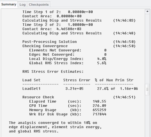
The stresses in the joint are lower now, but still reach over 100MPa in certain regions. 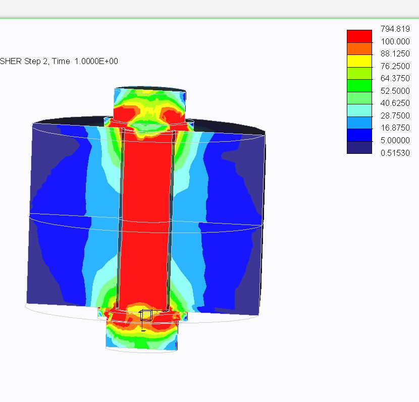
Do you know why the stress error is so big? Is it possible that my constraints are poorly set up? Z is the axial direction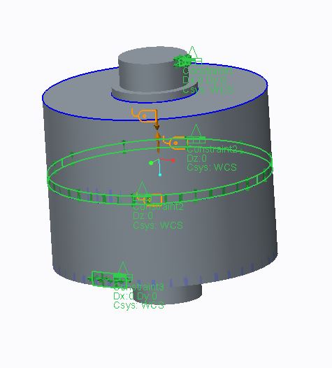
Best
Andreas
Nov 20, 2014
03:25 PM
- Mark as New
- Bookmark
- Subscribe
- Mute
- Subscribe to RSS Feed
- Permalink
- Notify Moderator
Please log in to access translation
Nov 20, 2014
03:25 PM
I could be from your constraints; I'm looking at the last picture you posted and am not entirely clear what you're trying to do with them. Can you post your model?
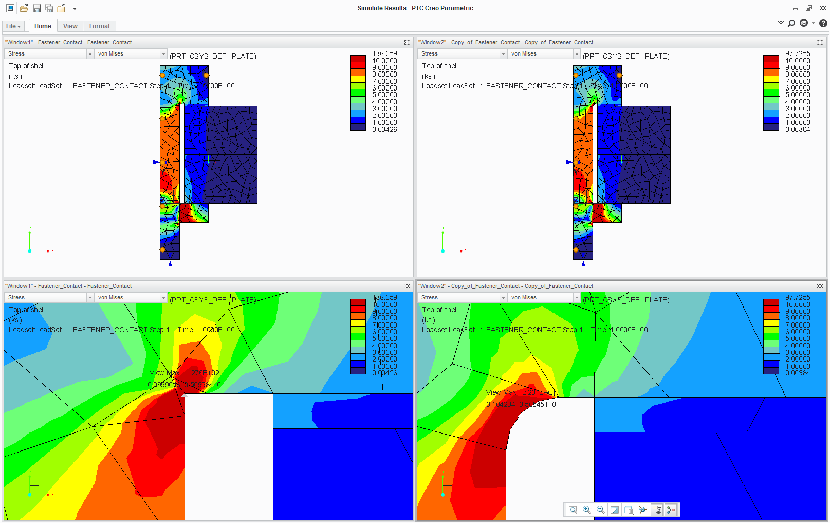
It's also very likely that you have a stress singularity due to a re-entrant corner. Stress singularities are something innate to the finite element method and every software package out there, but they are particularly problematic for the p-version of the finite element method with automated convergence algorithms. Dealing with stress singularities is rather tricky, but in the case of a re-entrant corner (a sharp inner 90 deg corner) one method to resolve the issue is to add a fillet. Below shows the same 2D axisymmetry contact model with the same convergence criteria; the only difference is the addition of a fillet at the top of the bolt where the shank meets the threads. The peak stress with a fillet is almost 1/5th of that without a fillet.
Nov 21, 2014
03:01 AM
- Mark as New
- Bookmark
- Subscribe
- Mute
- Subscribe to RSS Feed
- Permalink
- Notify Moderator
Please log in to access translation
Nov 21, 2014
03:01 AM
Thanks again for your quick response,
See my model attached. I tried to insert a rounding at the indicated position, but the my model failes to mesh. I also tried a chamfer, but that made the stresses worse.
Feel free to edit the constraining, fillet, etc and re-upload it.
thanks a lot in advance
Nov 21, 2014
08:51 AM
- Mark as New
- Bookmark
- Subscribe
- Mute
- Subscribe to RSS Feed
- Permalink
- Notify Moderator
Please log in to access translation
Nov 21, 2014
08:51 AM
Try adding 3 almost 0 stiffness ground springs to each part to stablize the parts for the start of the run.
Don Anderson
Nov 21, 2014
10:24 AM
- Mark as New
- Bookmark
- Subscribe
- Mute
- Subscribe to RSS Feed
- Permalink
- Notify Moderator
Please log in to access translation
Nov 21, 2014
10:24 AM
Hi Don,
thank you for your answer. I ran your model. I still have a stress error of over 30%. Did you leave the constraints as they were or do you want me to change them?
Best Andreas
Nov 21, 2014
11:05 AM
- Mark as New
- Bookmark
- Subscribe
- Mute
- Subscribe to RSS Feed
- Permalink
- Notify Moderator
Please log in to access translation
Nov 21, 2014
11:05 AM
Andreas,
I left the constraints as you had them as I do not have enough background on the system being tested to determine what's required for the simulation.
Don
Nov 24, 2014
02:29 AM
- Mark as New
- Bookmark
- Subscribe
- Mute
- Subscribe to RSS Feed
- Permalink
- Notify Moderator
Please log in to access translation
Nov 24, 2014
02:29 AM
Don,
The purpose of the model is to find a way to accuratly simulate the stresses that occur in a joint through a prestressed bolt. Whatever you must change in the model to achieve that is appreciated. At the moment, I get stress errors of around 30%, or 300MPa (in absolut numbers).
Andreas
Dec 05, 2014
04:25 PM
- Mark as New
- Bookmark
- Subscribe
- Mute
- Subscribe to RSS Feed
- Permalink
- Notify Moderator
Please log in to access translation
Dec 05, 2014
04:25 PM
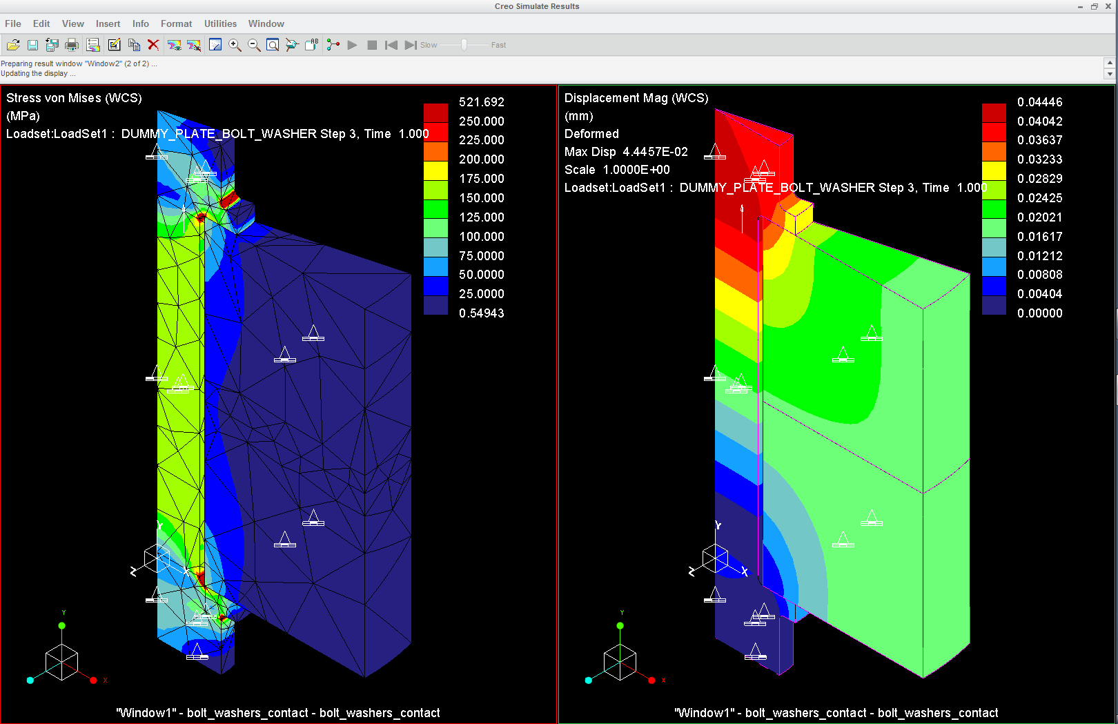
Here's the results from a modified model I made for your parts. I'll try to upload the model later.
Nov 25, 2014
04:16 AM
- Mark as New
- Bookmark
- Subscribe
- Mute
- Subscribe to RSS Feed
- Permalink
- Notify Moderator
Please log in to access translation
Nov 25, 2014
04:16 AM
Hi Steven,
I used the preload feature on the component as a hole( I modelled bolt, nut and washers as one part). (I also defined a measure to adjust the preload value.)
You are right, my main interest ist the stress distribution in the plates.
Your results look very well. Would you mind posting your model so I can see how you did it in detail?
Best Andreas


