
Turn on suggestions
Auto-suggest helps you quickly narrow down your search results by suggesting possible matches as you type.
Showing results for
Please log in to access translation
Turn on suggestions
Auto-suggest helps you quickly narrow down your search results by suggesting possible matches as you type.
Showing results for
Community Tip - Visit the PTCooler (the community lounge) to get to know your fellow community members and check out some of Dale's Friday Humor posts! X
- Community
- Creo+ and Creo Parametric
- 3D Part & Assembly Design
- Re: Style state in a drawing
Translate the entire conversation x
Please log in to access translation
Options
- Subscribe to RSS Feed
- Mark Topic as New
- Mark Topic as Read
- Float this Topic for Current User
- Bookmark
- Subscribe
- Mute
- Printer Friendly Page
Style state in a drawing
Oct 08, 2013
02:35 AM
- Mark as New
- Bookmark
- Subscribe
- Mute
- Subscribe to RSS Feed
- Permalink
- Notify Moderator
Please log in to access translation
Oct 08, 2013
02:35 AM
Style state in a drawing
In my assembly a have assigned some parts whit a hidden line. These parts are only used as a reference. I want to show the assembly in a drawing. The hidden lines (style) are not showed.
How can I display the style in a drawing?
Solved! Go to Solution.
Labels:
- Labels:
-
Assembly Design
- Tags:
- style
ACCEPTED SOLUTION
Accepted Solutions
Oct 08, 2013
08:48 AM
- Mark as New
- Bookmark
- Subscribe
- Mute
- Subscribe to RSS Feed
- Permalink
- Notify Moderator
Please log in to access translation
Oct 08, 2013
08:48 AM
I don't think you can access the 'styles' you create in assy mode for drawing views, unfortunately.
What you can do is set a component to be phantom.
- On the layout tab, select 'Component Display from the 'Edit' section.
- Look, the Menu Manager! Select 'Style' in the top section and at the bottom whatever best reflects where you want it shown as phantom - Picked View, This Sheet or All Sheets.
- Select the item(s) you want as phantom
- Middle mouse for done when you've picked all the components you want and a new section of the menu manager will appear.
- There you can select whether you want it standard, phantom opaque, phantom transparent or a user color.
You can also repeat those steps but select HLR display to control the display of hidden lines per component or individually blank or unblank components. The HLR display doesn't change the entire component to hidden, only allows you to control hidden line removal on a per component basis.
20 REPLIES 20
Oct 08, 2013
02:42 AM
- Mark as New
- Bookmark
- Subscribe
- Mute
- Subscribe to RSS Feed
- Permalink
- Notify Moderator
Please log in to access translation
Oct 08, 2013
02:42 AM
This looks like a screenshot from Creo Elements Direct. Or is this Creo Parametric?
Oct 08, 2013
02:44 AM
- Mark as New
- Bookmark
- Subscribe
- Mute
- Subscribe to RSS Feed
- Permalink
- Notify Moderator
Please log in to access translation
Oct 08, 2013
02:44 AM
It is Creo Parametric 2.0
Oct 08, 2013
02:51 AM
- Mark as New
- Bookmark
- Subscribe
- Mute
- Subscribe to RSS Feed
- Permalink
- Notify Moderator
Please log in to access translation
Oct 08, 2013
02:51 AM
Okay, I didn't recognize the menu on the right.
I haven't tried this too much but I have done overlayed views although in your case, that may not work as the lines will always be on top of the shaded images.
Have you tried specifying view states and seeing if you can pull those states into the drawing?
Oct 08, 2013
02:58 AM
- Mark as New
- Bookmark
- Subscribe
- Mute
- Subscribe to RSS Feed
- Permalink
- Notify Moderator
Please log in to access translation
Oct 08, 2013
02:58 AM
I have tried a lot of options, but none of them worked, jet.
In the view manager I have create a style, Simple Rep and Orient. The can all be put together in “All”. This combined view can be imported in a drawing. Only the style is not imported! I have had contact whit my software supplier, they say that the style can not be imported…. There must be a way.
Oct 08, 2013
03:22 AM
- Mark as New
- Bookmark
- Subscribe
- Mute
- Subscribe to RSS Feed
- Permalink
- Notify Moderator
Please log in to access translation
Oct 08, 2013
03:22 AM
I am sitting here trying this now. You are right, this is a real challenge.
This is when I resort to desperate measures... 1st thought is to use shaded images but make the "tool" transparent to some acceptable level. That seems to work nicely. More work would mean laying the hidden line view over the shaded view and erasing all the crossing lines and dragging out the sketch tools (NONO... not the sketch tools!)... yep, had to do that before.
I noticed that all the drawing tools only act on non-shaded drawing views. So if you didn't need the shaded parts, you would have it made.
I'd say PTC still has some work to do here. I had a similar problem with exploded view extension lines. In the no-hidden line mode, the hidden lines would hide appropriately... but in shaded mode, they wouldn't hide properly. I found that I could overlay a no-hidden view on top of non-edge shaded views to get the best of both worlds. Twice the work, twice the data, twice the print time... but the explode extension lines hid themselves.
If it is acceptable, I would opt for transparent parts in what you are working with. Quick and easy.
Oct 08, 2013
03:28 AM
- Mark as New
- Bookmark
- Subscribe
- Mute
- Subscribe to RSS Feed
- Permalink
- Notify Moderator
Please log in to access translation
Oct 08, 2013
03:28 AM
...oh, and if you didn't need the hidden line on the "tool parts" (non-shaded), you could have the "primary parts" in a non-edge shaded view. Then overlay a no-hidden view. Just Blank all the parts in the shaded view that you do not wish to have shown shaded. Now the wireframe overlay is properly displayed.
If the centers of your views are no longer equivalent, pick a feature to set the view origin in the properties dialog. Although you cannot pick vertices, you can pick just "past" a line to have it select the endpoint. I had to do this yesterday when I was overlaying detail views.
Oct 08, 2013
03:29 AM
- Mark as New
- Bookmark
- Subscribe
- Mute
- Subscribe to RSS Feed
- Permalink
- Notify Moderator
Please log in to access translation
Oct 08, 2013
03:29 AM
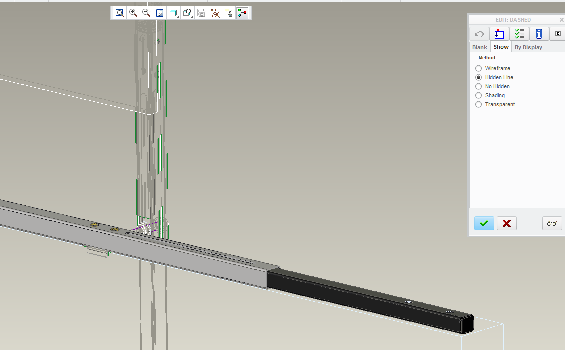
BTW: where is that dialog you show in the image? I don't see it in M040.
Oct 08, 2013
03:33 AM
- Mark as New
- Bookmark
- Subscribe
- Mute
- Subscribe to RSS Feed
- Permalink
- Notify Moderator
Please log in to access translation
Oct 08, 2013
03:33 AM
In the view manager, tabb Style, edit and redifine. I have M030
Oct 08, 2013
03:44 AM
- Mark as New
- Bookmark
- Subscribe
- Mute
- Subscribe to RSS Feed
- Permalink
- Notify Moderator
Please log in to access translation
Oct 08, 2013
03:44 AM
Ah... thanks. I never liked that dialog 
Oct 08, 2013
03:59 AM
- Mark as New
- Bookmark
- Subscribe
- Mute
- Subscribe to RSS Feed
- Permalink
- Notify Moderator
Please log in to access translation
Oct 08, 2013
03:59 AM
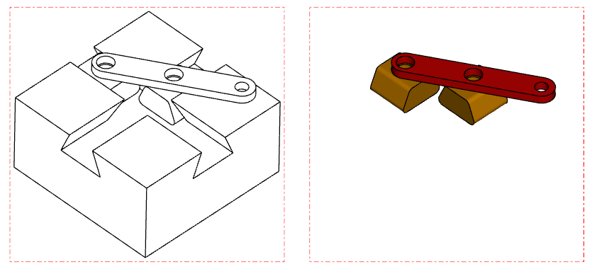
There is only a subtle difference between these two views... one is shaded with edges and the other is shaded only.
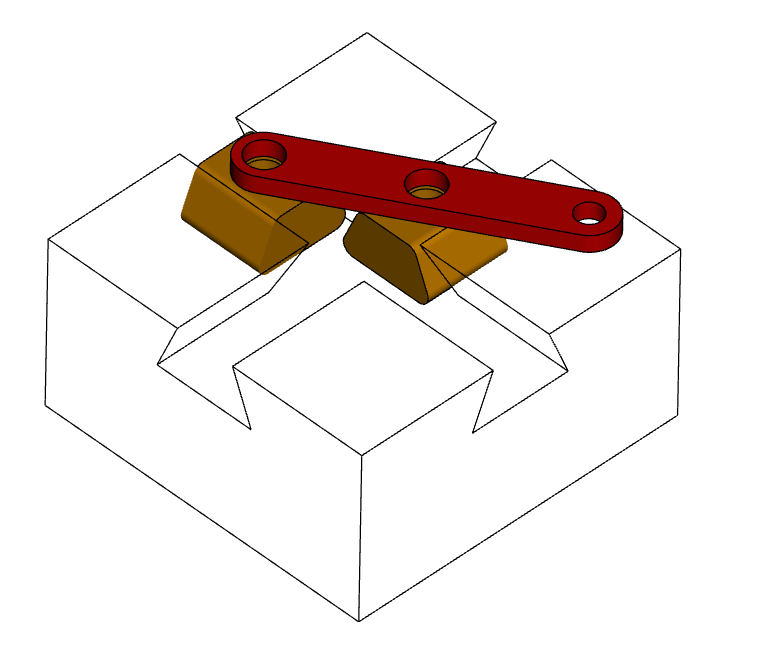
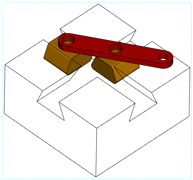
notice how everything goes haywire when I introduce hidden lines:

This is the two views side by side:
Just know that when things print to PDF, the shaded "images" are printed first with the wireframe stuff on top of it.
time for me to get some rest... hope this helps some.
Oct 08, 2013
04:03 AM
- Mark as New
- Bookmark
- Subscribe
- Mute
- Subscribe to RSS Feed
- Permalink
- Notify Moderator
Please log in to access translation
Oct 08, 2013
04:03 AM
Thanks for the quick reply and tips. Good night! I still have 7 hours of work to do.....
Jul 28, 2017
08:15 AM
- Mark as New
- Bookmark
- Subscribe
- Mute
- Subscribe to RSS Feed
- Permalink
- Notify Moderator
Please log in to access translation
Jul 28, 2017
08:15 AM
Is this still the only work arround?
Oct 08, 2013
03:30 AM
- Mark as New
- Bookmark
- Subscribe
- Mute
- Subscribe to RSS Feed
- Permalink
- Notify Moderator
Please log in to access translation
Oct 08, 2013
03:30 AM
Antonius, your desperate measures looks like a “cut and paste” option.
Your option for transparent parts, do you mean that I have to make the reference parts transparent in Render option? (assign a transparent material)
Oct 08, 2013
03:44 AM
- Mark as New
- Bookmark
- Subscribe
- Mute
- Subscribe to RSS Feed
- Permalink
- Notify Moderator
Please log in to access translation
Oct 08, 2013
03:44 AM
Not quite cut and paste, but careful manipulation of the views.
But yes, in the assembly model, I would assign transparency with the render dialog to the parts I want "unhighlighted".
Oct 08, 2013
08:48 AM
- Mark as New
- Bookmark
- Subscribe
- Mute
- Subscribe to RSS Feed
- Permalink
- Notify Moderator
Please log in to access translation
Oct 08, 2013
08:48 AM
I don't think you can access the 'styles' you create in assy mode for drawing views, unfortunately.
What you can do is set a component to be phantom.
- On the layout tab, select 'Component Display from the 'Edit' section.
- Look, the Menu Manager! Select 'Style' in the top section and at the bottom whatever best reflects where you want it shown as phantom - Picked View, This Sheet or All Sheets.
- Select the item(s) you want as phantom
- Middle mouse for done when you've picked all the components you want and a new section of the menu manager will appear.
- There you can select whether you want it standard, phantom opaque, phantom transparent or a user color.
You can also repeat those steps but select HLR display to control the display of hidden lines per component or individually blank or unblank components. The HLR display doesn't change the entire component to hidden, only allows you to control hidden line removal on a per component basis.
Oct 08, 2013
09:08 AM
- Mark as New
- Bookmark
- Subscribe
- Mute
- Subscribe to RSS Feed
- Permalink
- Notify Moderator
Please log in to access translation
Oct 08, 2013
09:08 AM
Hallelujah!!!!
This is it! So simple when you know it......
Thank you Doug,
Stefan
Oct 08, 2013
10:09 AM
- Mark as New
- Bookmark
- Subscribe
- Mute
- Subscribe to RSS Feed
- Permalink
- Notify Moderator
Please log in to access translation
Oct 08, 2013
10:09 AM
You're welcome. Hopefully PTC will get around to updating that dialog some time. I'm not holding my breath, though.
Oct 08, 2013
02:04 PM
- Mark as New
- Bookmark
- Subscribe
- Mute
- Subscribe to RSS Feed
- Permalink
- Notify Moderator
Please log in to access translation
Oct 08, 2013
02:04 PM
Doug, just curious... did you get this to work with shaded views?
For some reason, I could only do this with one of the wireframe|hidden|no-hidden views display states.
Oct 08, 2013
03:32 PM
- Mark as New
- Bookmark
- Subscribe
- Mute
- Subscribe to RSS Feed
- Permalink
- Notify Moderator
Please log in to access translation
Oct 08, 2013
03:32 PM
Same here, odd.
That looks like a bug. It'll let you go through the entire process with no errors, but it won't change the display. If you then change it to wireframe or no hidden the phantom lines show up.
I hadn't run into that because I rarely use shaded views in a drawing.
Oct 08, 2013
03:41 PM
- Mark as New
- Bookmark
- Subscribe
- Mute
- Subscribe to RSS Feed
- Permalink
- Notify Moderator
Please log in to access translation
Oct 08, 2013
03:41 PM
Okay, thanks. Its not just me then.
Shaded views was the one -huge- improvement over 2000i. My clients love it for presentation drawings.


