Community Tip - Want the oppurtunity to discuss enhancements to PTC products? Join a working group! X
- Community
- Creo+ and Creo Parametric
- 3D Part & Assembly Design
- Re: Surfacing Help: Style Surface Boundary Conditi...
- Subscribe to RSS Feed
- Mark Topic as New
- Mark Topic as Read
- Float this Topic for Current User
- Bookmark
- Subscribe
- Mute
- Printer Friendly Page
Surfacing Help: Style Surface Boundary Conditions
- Mark as New
- Bookmark
- Subscribe
- Mute
- Subscribe to RSS Feed
- Permalink
- Notify Moderator
Surfacing Help: Style Surface Boundary Conditions
I've been working more on this shroud (http://communities.ptc.com/thread/56128) and now I'm trying to figure out how to control the boundary conditions of a style surface.
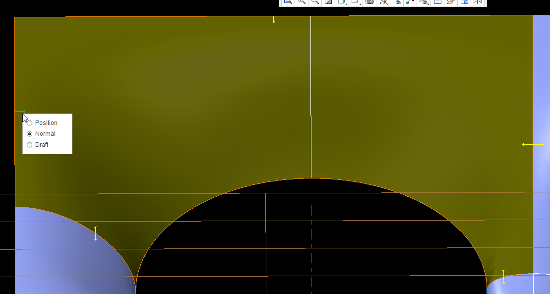
The boundary conditions at my edges where I have control curves are good (i.e. they are curvature continuous and normal to the plane, but in between control curves the surface does not keep that condition.

This becomes obvious when I thicken the surface with a normal offset. If the surface were normal, the part of the edge would be coincident with the horizontal red line (surface edge).
All of my edged except for those on the inner circle have edge control arrows. Why don't the arcs?
Solved! Go to Solution.
- Labels:
-
Surfacing
Accepted Solutions
- Mark as New
- Bookmark
- Subscribe
- Mute
- Subscribe to RSS Feed
- Permalink
- Notify Moderator
Ok, making progress.
First thing I found (and my first mistake) was thinking that the wireframe curves would be sufficient for defining the curvature was wrong.
Second, I found that the surfaces (even if the part won't actually have those physical surfaces) adjacent to the smooth (G2) surfaces must be defined. In my case, these were the two cylindrical surfaces that represent the final smooth airflow direction and the 'rim' type surfaces perpendicular to the airflow.
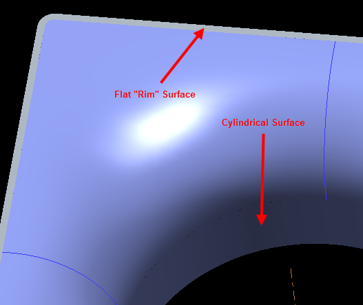
With those surfaces, I could then go and define the end points of my styles curves to be Continous.
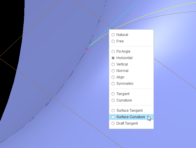
Then I could go and make connections between the style surfaces and my reference continuos surfaces by selecting the broken line indicators.

If more than one surface was possible, then you would get a prompt like this (asking if the red surface was the correct surface to connect to).
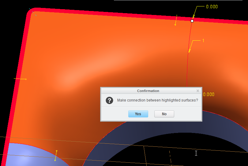
Once those connections were made, then I could set those connections to be surface continous (they defaulted to tangent).
Still have some investigation to do and cleanup, but this looks like a solid solution.
- Mark as New
- Bookmark
- Subscribe
- Mute
- Subscribe to RSS Feed
- Permalink
- Notify Moderator
Hi,
Use cylindrical surface instead of the arc curve to be able to set the boundary condition for the compound surface you are making.
If your curves don't have curvature continuous connections with the adjanced surfaces then the surface you are making won't be curvature continuous either.
- Mark as New
- Bookmark
- Subscribe
- Mute
- Subscribe to RSS Feed
- Permalink
- Notify Moderator
Not quite sure what you are meaning. I've attached the file so you can take a look.
The center circle is just that, a circle. The guide curves are style curves; planar, 3rd order, two points only with end point conditions of either horizontal or vertical.
- Mark as New
- Bookmark
- Subscribe
- Mute
- Subscribe to RSS Feed
- Permalink
- Notify Moderator
Ok, making progress.
First thing I found (and my first mistake) was thinking that the wireframe curves would be sufficient for defining the curvature was wrong.
Second, I found that the surfaces (even if the part won't actually have those physical surfaces) adjacent to the smooth (G2) surfaces must be defined. In my case, these were the two cylindrical surfaces that represent the final smooth airflow direction and the 'rim' type surfaces perpendicular to the airflow.

With those surfaces, I could then go and define the end points of my styles curves to be Continous.

Then I could go and make connections between the style surfaces and my reference continuos surfaces by selecting the broken line indicators.

If more than one surface was possible, then you would get a prompt like this (asking if the red surface was the correct surface to connect to).

Once those connections were made, then I could set those connections to be surface continous (they defaulted to tangent).
Still have some investigation to do and cleanup, but this looks like a solid solution.

- Mark as New
- Bookmark
- Subscribe
- Mute
- Subscribe to RSS Feed
- Permalink
- Notify Moderator
Be careful with mirrors. I am seeing some interpretation going on when you mirror with some assumptions. not every feature truly mirrors! I noticed this when I used curvature analysis but it was clear with the knot analysis...
the left is a mirror of the right where a C2 curvature was chanded to a simple arc.
This is actually a fairly disturbing development. the left side is the mirrored feature.
Both sides are treated equally. there is no reason for this to have developed differently. Each mirrored feature was investigated for commonality.
- Mark as New
- Bookmark
- Subscribe
- Mute
- Subscribe to RSS Feed
- Permalink
- Notify Moderator
Mirror the quilt instead of the features. Much more robust.
- Mark as New
- Bookmark
- Subscribe
- Mute
- Subscribe to RSS Feed
- Permalink
- Notify Moderator
Wow! THAT is very disturbing! Hey, PTC, I EXPECT things to mirror perfectly. I EXPECT pattern geometry to work perfectly. I do NOT expect this kind of garbage from what is priced as premium CAD software.
I've seen funny things, and geometry not working right, but never expected it to be this bad. Thanks for the in depth analysis Antonius! PTC should be paying you for developing their software for them...... ![]()
- Mark as New
- Bookmark
- Subscribe
- Mute
- Subscribe to RSS Feed
- Permalink
- Notify Moderator
This is scary indeed. I remember arguing the very opposite problem to this one with helical sweeps...
Thank you for the tip, Tom. I never knew you had the option to select only the quilt without its definition. Of course, smart is the default selection filter.
However, the right edge is a C2 blend giving the course rooster tail. Notice how it still softens this edge closer to radius. PTC is known for its surfacing prowess but my recent experiences say that it does a lot of fudging. Not as bad as the mirror of the geometry, but still something to note for those relying on curvature blends.
This is the same mirror with a quilt. Mirror is highlighted in green.
- Mark as New
- Bookmark
- Subscribe
- Mute
- Subscribe to RSS Feed
- Permalink
- Notify Moderator
Hmmm, I have a boundary blend I'm using on a handle for our new handpiece, and I simply mirrored that and merged them....and am having problems with the shell. Now, seeing this garbage, I think I'll make 2 separate boundary blends and merge that. Thanks for the analysis Antonius, It'll make me look closer at mine! ![]()
- Mark as New
- Bookmark
- Subscribe
- Mute
- Subscribe to RSS Feed
- Permalink
- Notify Moderator
It is odd that the mirror looks smoother. Accuracy seems to be affecting this as well. (Mirror is shown in green.)
Relative Accuracy - 0.001
Relative Accuracy - 0.00001
Absolute Accuracy - 0.000001
- Mark as New
- Bookmark
- Subscribe
- Mute
- Subscribe to RSS Feed
- Permalink
- Notify Moderator
You would think that the programmers would make this analysis instead of having to have the users do this.
Antonius - How much do you get paid from PTC for all the bugging, error fixing work arounds and miscellaneous things that you do? ![]()
![]()
- Mark as New
- Bookmark
- Subscribe
- Mute
- Subscribe to RSS Feed
- Permalink
- Notify Moderator
Get paid? Ha! I Pay!
Funny enough, I get better answers here on the cummunity than I get from tech support.
- Mark as New
- Bookmark
- Subscribe
- Mute
- Subscribe to RSS Feed
- Permalink
- Notify Moderator
...why would PTC pay for their programmers to do then when they can get customers to PAY THEM for the software and do it for them for free??? ![]()
- Mark as New
- Bookmark
- Subscribe
- Mute
- Subscribe to RSS Feed
- Permalink
- Notify Moderator
I've opened a tech support call on this. I would expect them to issue an SPR. If they do, I will post the details here.
- Mark as New
- Bookmark
- Subscribe
- Mute
- Subscribe to RSS Feed
- Permalink
- Notify Moderator
Thanks Dan. Attached is the file I am working with:
Creo 2.0 M040
Suppress the mirror and 3 merges and resume the previous features and you have the mirror of the feature rather than the quilt.
All the analysis are saved.
- Mark as New
- Bookmark
- Subscribe
- Mute
- Subscribe to RSS Feed
- Permalink
- Notify Moderator
I spoke extensively with Seshu from PTC Tech Support yesterday. He showed me some things that I did not know. (More detail to come)
- When merging surfaces, only merge two at a time, don't merge multple ones. (This allows you to control which edges becaome driving edges of the new surface)
- There are actually two edges that can be selected at the interface between two surfaces. Use Pick from List and analyze both. The one from the higher order surface is probably of better "quality" (smoothness).
- In this case, it would be the boundary blend surface as it is a higher order polynomial than the flat surface.
- Remember, all of these surfaces and edges are created using numerical methods, aka assumptions.
- Use the quilt that owns the higher quality edge as the first surface to select when merging. This will result in the higher order edge becoming the common edge or defning entity for the new merge.
This is what happened with Antonius' example above, his mirro ends up using the edge from the planar surface.
- Mark as New
- Bookmark
- Subscribe
- Mute
- Subscribe to RSS Feed
- Permalink
- Notify Moderator
Hmmmm, THAT'S interesting, thanks Dan. BUT, that shouldn't matter, and why aren't we told this in training? PTC touts the new ability to merge a bunch of surfaces at the same time (a new feature from previous versions), yet doesn't tell us about all the pitfalls??? Huh???
- Mark as New
- Bookmark
- Subscribe
- Mute
- Subscribe to RSS Feed
- Permalink
- Notify Moderator
That is good information, Dan. I usually fumble through getting the feature to work rather than worry about which is which in the list.
- Mark as New
- Bookmark
- Subscribe
- Mute
- Subscribe to RSS Feed
- Permalink
- Notify Moderator
That is really good to know.
I was told to not use the multi merge feature, but that's propably cause I've never got properly trained, and went straight onto the advanced (I'd call that necesarry) stuff back when i started with Creo.
I've never heard about the higher polynomial or higher quality edge matter in case of surface geometry merge.
Glad I still read the forums.
- Mark as New
- Bookmark
- Subscribe
- Mute
- Subscribe to RSS Feed
- Permalink
- Notify Moderator
I think if it matters, then the UI should be providing some level of control over this. Either a warning or a toggle... built-in curvature integrigation, or some other level of letting the user know they -may- be doing something stupid.
- Mark as New
- Bookmark
- Subscribe
- Mute
- Subscribe to RSS Feed
- Permalink
- Notify Moderator
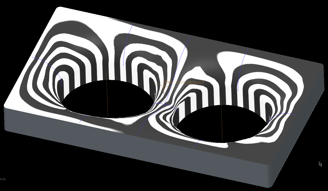
I usually notice that surfaces are not exact copies or exact mirrored copies by looking at their isocurves.
The right side is the mirrored side, and as you can see on the picture it's topology is slightly different.
It'd propably be better to avoid mirror feature and use copy and paste special transformation instead, or maybe FMX mirror would do the right job. Not sure.
One question, how does the Flip Normal feature work in Creo Parametric? I can't seem to be able to edit it's definition.
- Mark as New
- Bookmark
- Subscribe
- Mute
- Subscribe to RSS Feed
- Permalink
- Notify Moderator
If an industrial design guy saw this, he might have a fit ![]()
Did you mirror the quilt instead of the feature, Jakub?
- Mark as New
- Bookmark
- Subscribe
- Mute
- Subscribe to RSS Feed
- Permalink
- Notify Moderator
I used one of your models, Tom. It propably doesn't matter, the mirror feature is just all wrong.
If the designer poked one of his eyes before looking at the picture then yeah he might have a fit ![]()
- Mark as New
- Bookmark
- Subscribe
- Mute
- Subscribe to RSS Feed
- Permalink
- Notify Moderator
Tom Uminn's comment above is indeed a very valuable tip. Mirroring the quilt does make a significant difference over mirroring the feature. And yes, mirrors are very iffy if you don't go back and confirm what it really did.


