
Turn on suggestions
Auto-suggest helps you quickly narrow down your search results by suggesting possible matches as you type.
Showing results for
Please log in to access translation
Turn on suggestions
Auto-suggest helps you quickly narrow down your search results by suggesting possible matches as you type.
Showing results for
Community Tip - Need to share some code when posting a question or reply? Make sure to use the "Insert code sample" menu option. Learn more! X
Translate the entire conversation x
Please log in to access translation
Options
- Subscribe to RSS Feed
- Mark Topic as New
- Mark Topic as Read
- Float this Topic for Current User
- Bookmark
- Subscribe
- Mute
- Printer Friendly Page
Sweep ?
Oct 08, 2013
05:21 PM
- Mark as New
- Bookmark
- Subscribe
- Mute
- Subscribe to RSS Feed
- Permalink
- Notify Moderator
Please log in to access translation
Oct 08, 2013
05:21 PM
Sweep ?
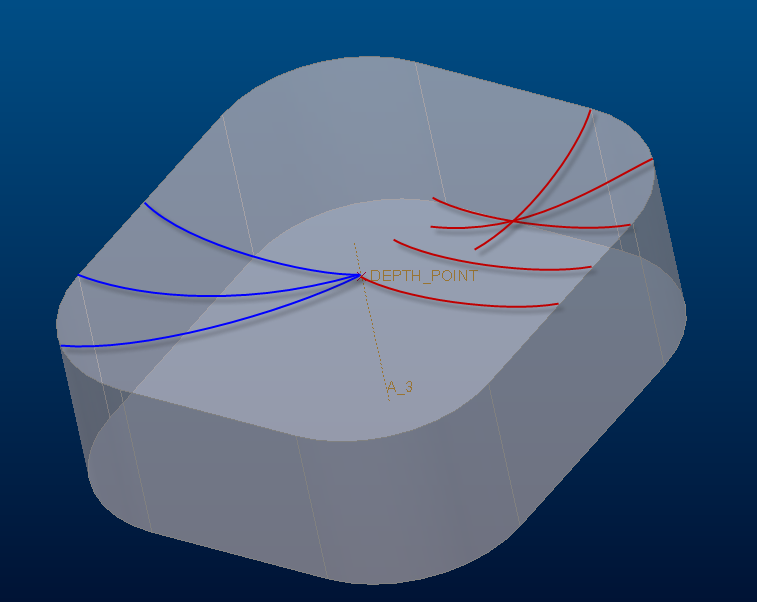
I have a user that wants to have a variable section sweep that creates a “cup” geometry to mimic what is seen on LEDs. However in Creo I can’t get the section to be perpendicular to the axis and trajectory. See below. I want a cup like what is shown in the blue lines, but all I can seem to get is interference in the corners as shown with the red lines. He can do a rotated cup, but that wont include the corners of the square in the “cup”. Any ideas for us?
This thread is inactive and closed by the PTC Community Management Team. If you would like to provide a reply and re-open this thread, please notify the moderator and reference the thread. You may also use "Start a topic" button to ask a new question. Please be sure to include what version of the PTC product you are using so another community member knowledgeable about your version may be able to assist.
Labels:
- Labels:
-
General
5 REPLIES 5
Oct 08, 2013
07:49 PM
- Mark as New
- Bookmark
- Subscribe
- Mute
- Subscribe to RSS Feed
- Permalink
- Notify Moderator
Please log in to access translation
Oct 08, 2013
07:49 PM
You are on the right track but you need to lock the center point in the sketch.
Have a look at this thread: Create hex/pentagon shaped dimples on a circular surface.
If you scroll further to the bottom you will find an included PRT file (Creo 2.0 full version) of the honeycomb sweep.
Yours should be fairly straight forward to do what you need it to do.
Oct 08, 2013
09:32 PM
- Mark as New
- Bookmark
- Subscribe
- Mute
- Subscribe to RSS Feed
- Permalink
- Notify Moderator
Please log in to access translation
Oct 08, 2013
09:32 PM
You know, i always say its simple and it rarely is 
Indeed, there are a few tricks you must be aware of when using sweep.
In this case, the Sweep acts normal to the trajectory. In order to make the sweep revolve around the axis, you need a circular trajectory (Origin). The periphery is a "guide chain" (Chain 1; rule bases tangent). Further more, the endpoint of Chain 1 needs to be in line with the endpoint of the trajectory circle (Origin). If you divide the midpoint of the line in the Extrude sketch, you will have an endpoint there to align with the circle. Orienting the sketch for the circle will also let the circle align properly (without adding an additional Divide).
For the sweep sketch, note that you don't even have to touch the selected Origin. Inn the example attached, the arc is attached to the edge and to the axis reference.
So what happens now is that the circle defines the normal direction, but the section sketch follows its references.
Hope all that makes sense.
The attached file is Creo 2.0 full version.
Oct 09, 2013
08:49 AM
- Mark as New
- Bookmark
- Subscribe
- Mute
- Subscribe to RSS Feed
- Permalink
- Notify Moderator
Please log in to access translation
Oct 09, 2013
08:49 AM
What Tom said.
I'd add, this is not a Creo limitation, it's a geometry limitation. You cannot define a plane through the axis and normal to the outer edge at any point along that edge. A plane with those constraints only exists at six discreet points, one for each segment of the perimeter. The circle allows the plane to be normal at any point around the axis.
Oct 10, 2013
12:21 PM
- Mark as New
- Bookmark
- Subscribe
- Mute
- Subscribe to RSS Feed
- Permalink
- Notify Moderator
Please log in to access translation
Oct 10, 2013
12:21 PM
Thanks a bunch guys. You guys are a great help. Damian and Ron over on the exploders came up with the solution we went with though.
http://portal.ptcuser.org/p/fo/st/thread=41018
Video:
http://www.youtube.com/watch?v=upBZkdF9n3w&feature=c4-overview&list=UU89vS9l-hjWue8YteZ56esA
Oct 10, 2013
12:43 PM
- Mark as New
- Bookmark
- Subscribe
- Mute
- Subscribe to RSS Feed
- Permalink
- Notify Moderator
Please log in to access translation
Oct 10, 2013
12:43 PM
Also a great solution. Thanks for sharing that, Andrew.


