
Turn on suggestions
Auto-suggest helps you quickly narrow down your search results by suggesting possible matches as you type.
Showing results for
Please log in to access translation
Turn on suggestions
Auto-suggest helps you quickly narrow down your search results by suggesting possible matches as you type.
Showing results for
Community Tip - Need to share some code when posting a question or reply? Make sure to use the "Insert code sample" menu option. Learn more! X
- Community
- Creo+ and Creo Parametric
- 3D Part & Assembly Design
- Re: Swept blend through projected sketches
Translate the entire conversation x
Please log in to access translation
Options
- Subscribe to RSS Feed
- Mark Topic as New
- Mark Topic as Read
- Float this Topic for Current User
- Bookmark
- Subscribe
- Mute
- Printer Friendly Page
Swept blend through projected sketches
Sep 19, 2017
09:47 AM
- Mark as New
- Bookmark
- Subscribe
- Mute
- Subscribe to RSS Feed
- Permalink
- Notify Moderator
Please log in to access translation
Sep 19, 2017
09:47 AM
Swept blend through projected sketches
Hi,
I'm trying to do a swept blend through 5 sketches, 2 of these sketches are projected on surfaces. The swept blend doesn't work when these 2 sketches are selected. When not selected it works fine. How can I solve this problem? I have attached a .prt file. The sketches are vane1_sketch_projection, vane2_sketch,vane3_sketch,vane4_sketch and vane5_sketch_projection. Thanks
Labels:
- Labels:
-
General
8 REPLIES 8
Sep 19, 2017
11:43 AM
- Mark as New
- Bookmark
- Subscribe
- Mute
- Subscribe to RSS Feed
- Permalink
- Notify Moderator
Please log in to access translation
Sep 19, 2017
11:43 AM
I can't open Creo 4 files, so I don't know if your vane1_sketch_projection and vane5_sketch_projection are actually not sketches but projections of sketches onto a non-planar surface?
If so, then I think the problem might be that you cannot use non-planar sections for the swept-blend modeling feature. I don't know this for sure - the system allowed me to use non-planar closed curve as a "selected section", but then the swept blend feature failed. When I redefined this curve to be from a projection onto a flat surface, the feature worked.
Further references: PTC Creo Parametric Help - swept blend
Suggestions:
1) generate planar projections of the vane1_sketch_projection and vane5_sketch_projection onto appropriate datum planes
2) use surface modeling tools such as styles, boundary blends and fills; merge the surfaces into a quilt that encloses a volume and solidify it.
Sep 20, 2017
04:08 PM
- Mark as New
- Bookmark
- Subscribe
- Mute
- Subscribe to RSS Feed
- Permalink
- Notify Moderator
Please log in to access translation
Sep 20, 2017
04:08 PM
Hi
I solved the problem. I deleted the projected profiles and instead used the swept blend with two additional profiles to go beyond the curved walls. After that I used extrude cut to remove the excess segments of the wings.
Sep 20, 2017
04:34 PM
- Mark as New
- Bookmark
- Subscribe
- Mute
- Subscribe to RSS Feed
- Permalink
- Notify Moderator
Please log in to access translation
Sep 20, 2017
04:34 PM
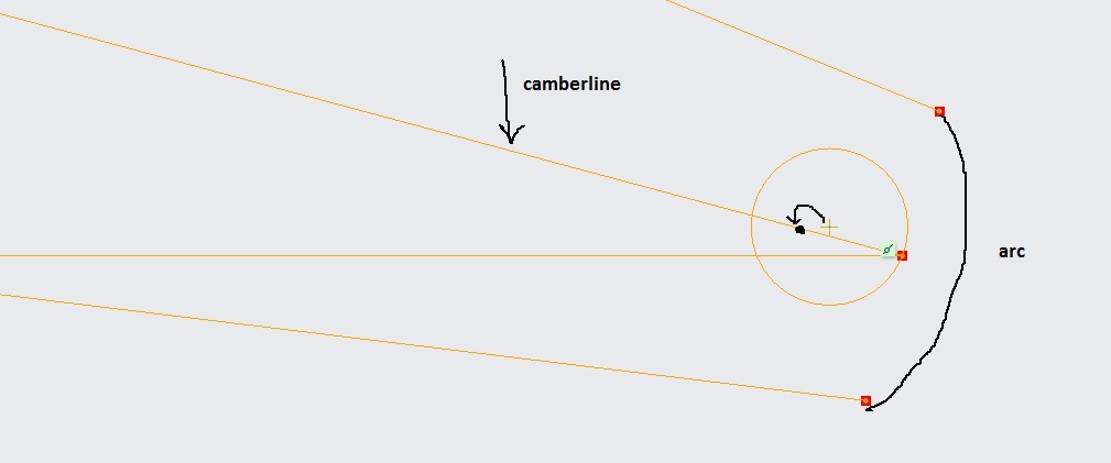
I just have one last issue to solve which is very surprising to me actually. I have attached a sketch file to this post. I'm trying to draw a trailing edge circle such that it's center resides on the camber line with the circle passing through the last point of the camber line. I tried to use the coincident constraint between the center of circle and the camberline but it didn't work. Also, upper and lower curves should be connected with an arc to close the sketch. I wasn't successfull with this either. Any help is appreciated.
Sep 20, 2017
04:51 PM
- Mark as New
- Bookmark
- Subscribe
- Mute
- Subscribe to RSS Feed
- Permalink
- Notify Moderator
Please log in to access translation
Sep 20, 2017
04:51 PM
It would be helpful to all who read this forum if you posted some screenshots to describe your problem. As they say, picture is worth 1000 words...
Sep 20, 2017
05:17 PM
- Mark as New
- Bookmark
- Subscribe
- Mute
- Subscribe to RSS Feed
- Permalink
- Notify Moderator
Please log in to access translation
Sep 20, 2017
09:19 PM
- Mark as New
- Bookmark
- Subscribe
- Mute
- Subscribe to RSS Feed
- Permalink
- Notify Moderator
Please log in to access translation
Sep 20, 2017
09:19 PM
I'm sorry but your picture leaves me guessing... what is the horizontal line and why isn't its endpoint coincident with the endpoint of the camber line?
where are the dimensions?
and finally, what do you mean by "it didn't work?" - did the system give you any feedback in the message log area, or what exactly happened when you tried to apply your constraints?
anyway -
did you try drawing an unattached circle and 1st constrain its center to the camber line and then constrain it to be coincident with the endpoint of the camber line?
for the arc, can you manage to get an arc that connects the line segments (that is, without tangency) ?
Then apply the tangent constraints afterward.
Sep 27, 2017
06:00 PM
- Mark as New
- Bookmark
- Subscribe
- Mute
- Subscribe to RSS Feed
- Permalink
- Notify Moderator
Please log in to access translation
Sep 27, 2017
06:00 PM
Sorry for the late response. The horizontal line is the chord and it is coincident with the camberline. I want 2 circles with the same condition. A leading edge circle which is tangent to the suction and pressure side curves and passes through the first point of the camberline. A trailing edge circle which is again tangent to the suction and pressure side curves and passes through the last point of the camberline. I drew 2 unattached circles and then I tried to use the tangent constraint. I selected the circle and suction side curve and nothing happened. I defined the circle using analytical expressions. However, I wasn't able to use the tangency. I don't know why this is happening. Is there something wrong with CREO?
Oct 01, 2017
12:28 PM
- Mark as New
- Bookmark
- Subscribe
- Mute
- Subscribe to RSS Feed
- Permalink
- Notify Moderator
Please log in to access translation
Oct 01, 2017
12:28 PM
I've found what the problem was, which prevented me from using coincident and tanget constraints. My approach to create the airfoil was to create 3 splines (without being concerned about the exact shape of them, just clicking at random points to create the splines) for the suction side, camberline and pressure side curves. Then replace these splines with a .prt file for each to obtain the exact shape of the airfoil. With this approach I wasn't able to use the coincident and tangent constraints. The work around was to import .prt files containing the coordinates of the suction side, camberline and pressure side curves, and then create a datum curve through the points and then create a sketch and project the curves into the sketch. In this approach the mentioned constraints work fine. However, a new issue arises. I closed the trailing edge of the suction and pressure side curves with a tangent arc. I've done this 2 times for two airfoils. Now that I wan't to use the swept blend feature, the software doesn't recognizes these arcs. As such the swept blend fails. Does anybody know how to fix this problem? I've attached a zip file to this post.


