
Turn on suggestions
Auto-suggest helps you quickly narrow down your search results by suggesting possible matches as you type.
Showing results for
Please log in to access translation
Turn on suggestions
Auto-suggest helps you quickly narrow down your search results by suggesting possible matches as you type.
Showing results for
Community Tip - Stay updated on what is happening on the PTC Community by subscribing to PTC Community Announcements. X
- Community
- Creo+ and Creo Parametric
- 3D Part & Assembly Design
- The Creo Launch – An Insider’s Scoop
Translate the entire conversation x
Please log in to access translation
Options
- Subscribe to RSS Feed
- Mark Topic as New
- Mark Topic as Read
- Float this Topic for Current User
- Bookmark
- Subscribe
- Mute
- Printer Friendly Page
The Creo Launch – An Insider’s Scoop
Jan 02, 2011
11:40 AM
- Mark as New
- Bookmark
- Subscribe
- Mute
- Subscribe to RSS Feed
- Permalink
- Notify Moderator
Please log in to access translation
Jan 02, 2011
11:40 AM
The Creo Launch – An Insider’s Scoop
You can read the Desktop Tip of the Month here also authored by Jon Jarvis and you can also read the Enterprise Product Focus of the Month here and the Enterprise Tip of the Month here authored by Bruce Hulse.
| PTC Technical Specialists Newsletter - January 2011 |
Product Focus : The Creo Launch – An Insider’s Scoop |
|---|
Name. Its significance cannot be overestimated. During my life, it announced some of the most significant events in my 41 years. When I was born, I received a name, and for some of us, when we married our name changed. It’s not just something that is done without thought or care.
On October 28, 2010, PTC changed the name of three of its flagship products – Pro/ENGINEER, CoCreate, and ProductView. Why? Something of major significance had been announced – just like the birth of a child or the wedding of a son or daughter. PTC unveiled a vision with a solid strategy & technology that will greatly unlock the potential for organizations by unleashing creativity, facilitating teamwork, increasing efficiency and ultimately realizing value. During the last 17 years of my professional career, I have been an application specialist for PTC and worked with hundreds of PTC customers both large and small and helping them optimize their current product development processes. I was there in the early days in the 1990’s when PTC had the most compelling offering for product design as the first and only 3D parametric, associative CAD software. I was also around when Windchill was first developed as an important enabler for companies for Product Lifecycle management. And now, 17 years later, I got a front row seat in Boston, Massachusetts at the Park Plaza Castle to see the unveiling of Creo. I’m so glad I did. Let me tell you my inside scoop: from someone who is professionally invested and wants to see all our customers succeed in this competitive design environment we find ourselves in today.
The event started with loud sirens and four men dressed in orange jumpsuits being escorted to a prison. The four men, with names branded on their back – Creativity, Teamwork, Efficiency and Value, were all in lockdown. Then atop a high platform, our host asked us one simple question? “Why are we here – feeling in prison? The answer – because of CAD (2D, 3D, Direct, Parametric). There has been a lot of good that has come with CAD, however, with those gains, the potential of individuals, organizations and products themselves has been held back by the same challenges that have existed for 20 years. But that’s OK, because over time, the CAD industry has accepted it. These are the tradeoffs users have made and this is the way it is, and this is the way it will always be.” Then, over the loudspeaker, a voice said “No, not anymore, there is a better way!” See Figure 1.

Figure 1: Creativity, Teamwork, Efficiency and Value are all in lockdown
Market Strategy behind Creo
James Heppelmann, PTC President and Chief Executive Officer’s, first words to the audience were “What an exciting day to be a PTC Customer, a PTC Employee or part of this industry that brought us together this day.” After some formal welcomes to both the audience onsite as well as the thousands of people watching through the virtual event on the web, James Heppelmann made a bold proclamation that “this launch will be the biggest innovation in the CAD industry since Samuel Geisberg brought Pro/ENGINEER to the market in 1987, more than 20 years ago.” See Figure 2.
Figure 2: James Heppelmann, PTC President and Chief Executive Officer
He then talked to the audience about the CAD market to explain what PTC is doing. Designs, for thousands of years, have been developed in 2D. Then about 100 years ago, Eli Whitney introduced the concept of standardization of parts, which drove the need for a 2D drawing to describe each part perfectly so that they could be assembled together. Then when the computer came along, someone suggested these 2D drawings could be drawn on the computer and hence the CAD industry was born. This established the first major component of the CAD – 2D Drafting. There were many companies that got into this industry, including our own company – CoCreate (formerly part of Hewlett Packard). Then in 1987, PTC launched an incredible breakthrough. The first, 3D parametric, feature –based, solid modeler called Pro/ENGINEER. This established the second major component of CAD – 3D Parametric Modeling. PTC also invented the concept of assembling these components together to make up a product into the third major component of CAD – Assembly Modeling. As much as we hoped for 2D to go away once 3D came along, those downstream on the factory floor or installing the product still needed a 2D drawing. Therefore, PTC invented the concept of 2D drawings being automatically developed from the 3D models. Hence the fourth major component of CAD was born – 2D from 3D. Also, in this group is 2D Schematics. Really what he is referring to there is the existence of smart, intelligent schematics that have parameters, generate intelligent reporting, and can drive 3D geometry like cables & pipes. Then basically, in the last 20 years or so, everyone in the industry adopted PTC concepts for CAD, both the good and the bad, and developed their versions of a parametric CAD tool with 2D drawings, 3D parametric modeling, and assembly modeling. However, one company went a different route than parametric design. They felt that parametrics, although good for building design intent, was too hard and complicated for the average user , so they pioneered a new concept of direct modeling where geometry is “king”. What you see, is what you get. This led to the fifth major component of CAD – Direct Modeling. And several other companies have since copied this concept to bring to market. See Figure 3.
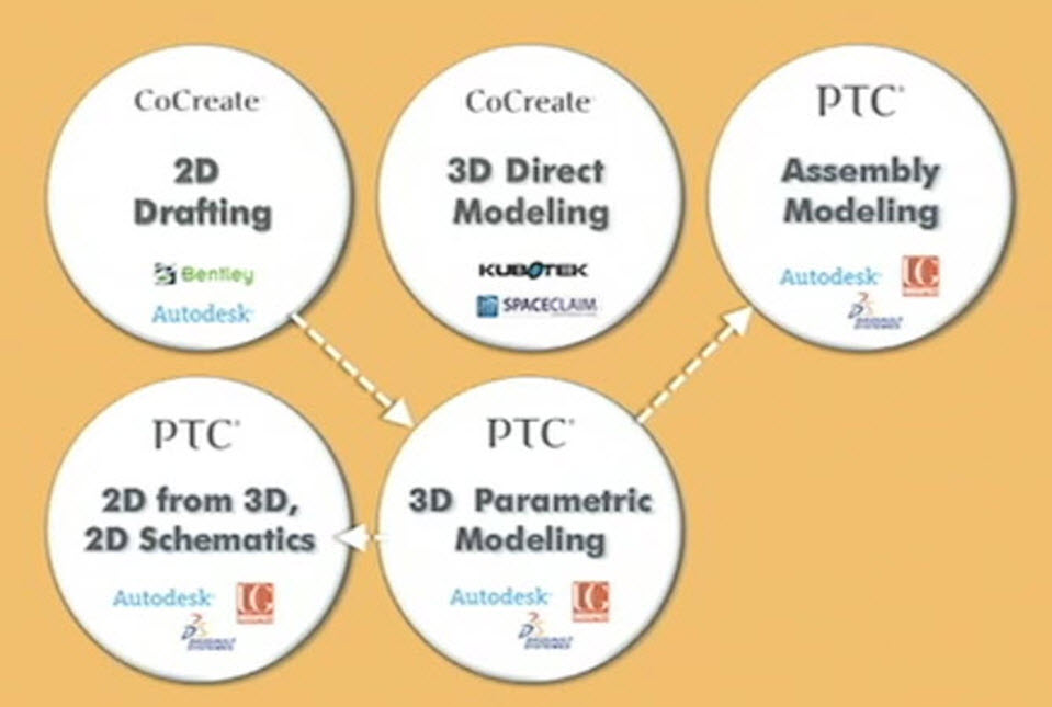
Figure 3: The key components of CAD today
From these key components, we uncovered that there are really three methods to design:
1) 2D design
2) 3D design
3) Assembly Design
Also, there are fundamentally two different approaches:
1) Direct Modeling and
2) Parametric Modeling
Direct modeling is a simple, easy approach where what you see, is what you get. There is no history for 2D drawings or 3D geometry that is created. Parametric Modeling is all about a sophisticated approach where your recipe or your design intent drives the geometry which is created and managed. However, as we look at the CAD methodology and approaches, there was an empty box. See Figure 4.
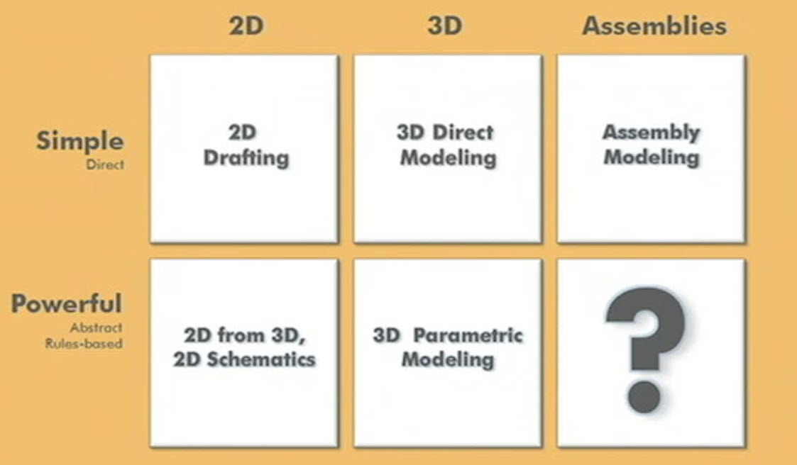
Figure 4: Three Methodologies and Two Approaches to CAD
Today, the idea that assembling components together in CAD works well for products that come in one or a small number of configurations. The problem is nobody is there anymore. Products are now offered with many options and variants, in multiple configurations with lots of variability and an endless number of design changes always coming. Real products today may have hundreds, thousands, even millions of multiple configurations. Who is going to model those in CAD? Today, no one can do this. There is a need for the last major component of CAD – Product Configuration Modeling. See Figure 5.
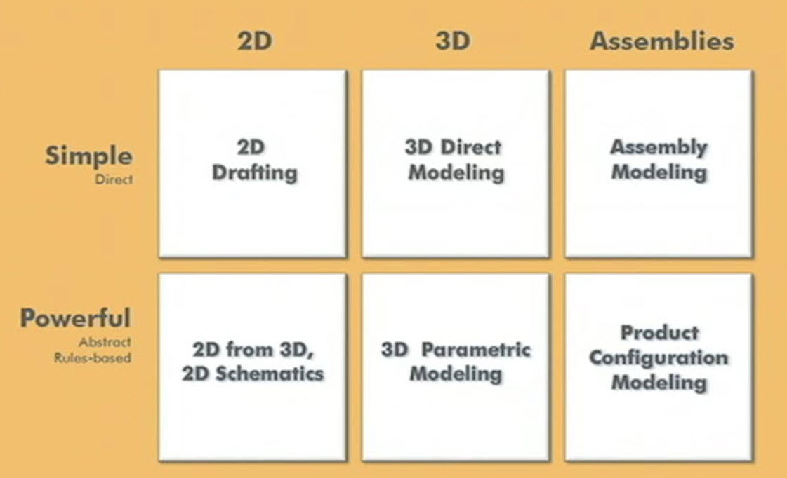
Figure 5: A need for Product Configuration Modeling which does not exist today
This is the current CAD market today as seen by our customers, competition, and industry analysts. Many would agree that the market is mature and this is the way it will always be. Then James Heppelmann asked his employees within the company “Are you sure all the problems are solved?” He quickly said “I really don’t think they are!” Basically, he feels that CAD companies have been working on and eventually ignoring these problems for the last 10 years because there has been little innovation in the market to solve them. He believes that there are still four, big, unsolved problems that lock up untapped potential in the areas of creativity, innovation, teamwork and value.
Ease of Use
The first big problem is Ease of Use. We live in a world of instant gratification where I can buy an IPod and download & play my first song in 7 minutes or less. He asked any new user to pick any 3D parametric CAD tool and see if they can do anything with the tool within the first week? He feels that it takes at least a week to figure out how the software works before you can start using it productively. What about the easy to use, direct tool? That tool, although, it’s simple, is not compatible with the parametric, sophisticated tool. Therefore, company always buy tools for their sophisticated users and the casual users end up having a tool that is overkill for them and too complicated to use. See Figure 6.
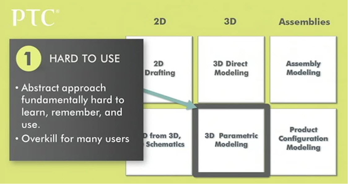
Figure 6: Parametric tools over-serve many of the users
Interoperability
The second big problem is Interoperability. Users cannot work effectively with a colleague, supplier, or customer, with different branded tools. Even within 3D parametrics, or 2D drafting, or between the paradigms of direct to parametric; these different tools sap productivity and innovation out of the system. This ultimately leads to the next major problem of technology lock-in. See Figure 7.
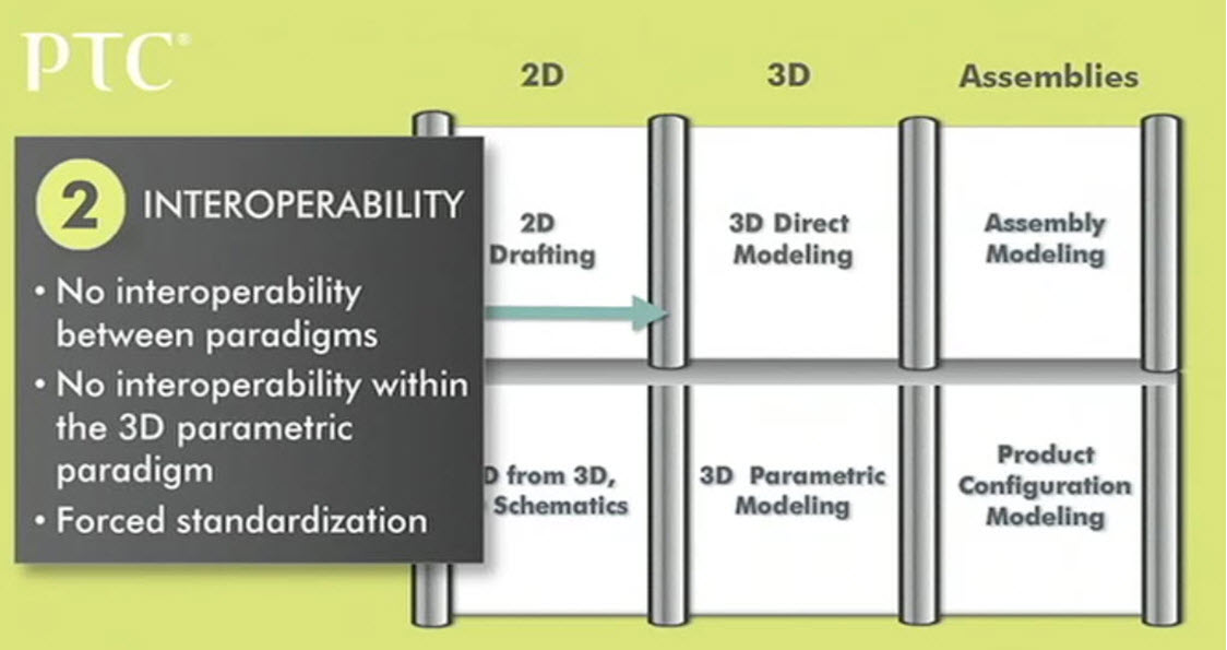
Figure 7: No interoperability between different branded systems makes it difficult to collaborate
Technology Lock-In
The third major problem is technology lock-in (i.e. switching cost). It doesn’t really matter if the CAD vendors innovate, because companies cannot justify a switch. Companies have invested so much in the last 10 years in their designs, and because tools are not interoperable, they cannot bring their designs forward, or if they do, with great pain and agony of redesign. For the CAD vendors this is good and bad. One, it drives customer loyalty to their products; however, it also destroys any incentive to innovate, because customers will not switch anyway. This has sapped the innovation out of the industry without them even knowing it was happening. See Figure 8.
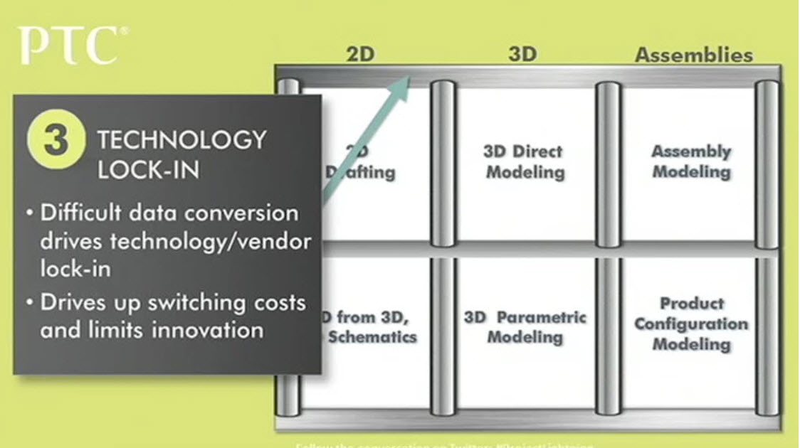
Figure 8: Difficult data conversion causes companies to not switch CAD tools
Realistic Assembly Modeling
The fourth and final major problem is product configuration modeling. Most customers have products that could come in thousands of configurations. How many of them were actually modeled in a CAD system? One, two, maybe a few representative examples may be modeled. And the rest of the configurations are done by interpolation, extrapolation and prayer. However, this caused problems for downstream deliverables like instruction manuals, drawings, and even physical prototypes because all of them are predicated on an assembly that was never modeled digitally. This is a big problem because companies cannot model serial numbers, because in today’s world it would kill them – they don’t have the manpower to produce all the data of all the hypothetical combinations of configurations of their products. See Figure 9.
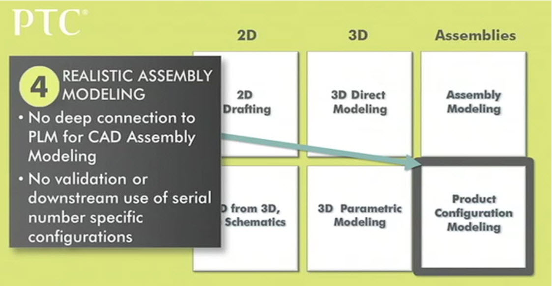
Figure 9: Product Configuration Modeling
So what is PTC doing about it? PTC is in a very unique and compelling position. PTC has is the innovator and leader in all 6 areas of the market. PTC has a viable product for 2D drafting in CoCreate. PTC has the best in class direct modeling in CoCreate. Both Pro/ENGINEER and CoCreate have simple assembly technology. PTC has the world’s best product configuration kernel in Windchill. PTC also has the best parametric modeler & sophisticated 2D from 3D in Pro/ENGINEER. PTC was the key innovator and a leader today in all areas of the CAD industry from 2D, 3D and assembly modeling in both simple/direct and rule-based, parametric. See Figure 10.
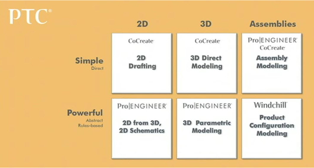
Figure 10: PTC unique position as an innovator and leader in all 6 areas of CAD
James Heppelmann’s final comments were “we are going back to the drawing board, start with a fresh sheet of paper, and we are going to unlock potential”
One letter falls from each of the four original words of creativity, teamwork, efficiency and value to form the name “Creo” A PTC Product. Creo is the Latin root for the word “create”. And in other languages in context it means “I think. I create. I believe.”
Creo will be PTC’s next generation design suite. It will be made of simple, role-specific apps to address the needs of 2D, 2D and assemblies in either a simple/direct way or powerful, parametric way.
Product Strategy for Creo
Brian Shepherd, Executive Vice President of Product Development, and Michael Campbell, Divisional Vice President of Creo Product Development, came on stage to tell the audience all about Creo and exactly how it will unlock potential. See Figure 11.

Figure 11: Michael Campbell and Brian Shepherd
Creo is a suite of interoperable, role-specific applications (apps), for all the different people in the product development process. These new apps are delivered on a brand new, open common data model which is the new architecture underlying Creo. This is going to be an open system that allows for data compatibility when working in a multi-CAD environment. Lastly, there is a robust, configuration kernel in Creo that unlock a new approach in assembly modeling which connects assemblies at the enterprise level with systems like Windchill and the design tool environment. See Figure 12.
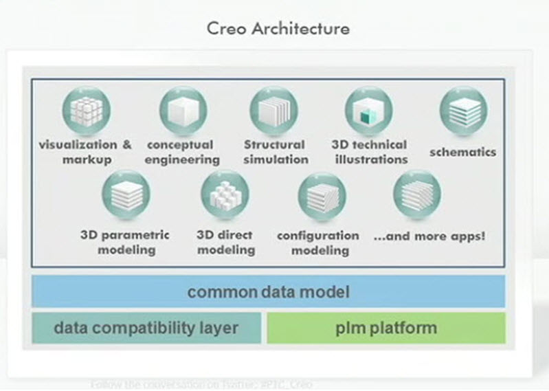
Figure 12: Creo Architecture
Creo brings forth four break-through technologies:
1) AnyRole Apps
2) AnyMode Modeling
3) AnyData Adoption
4) AnyBOM Assemblies
Each of these Creo technologies will help solve the four big problems of ease of use, interoperability, technology lock-in and realistic assembly modeling. See Figure 13.

Figure 13: Four Break Through Technologies in Creo
Creo is built on and derived from elements of PTC heritage of three market leading products of Pro/ENGINEER, CoCreate, and ProductView. But it is much more than just a repackaging of these existing products as PTC has many patent-pending new technologies to bring to market.
Next, Mike Campbell introduced a demonstration of the four technologies with live software, a real product dataset from Callaway Cars, and a demonstration team presenting onsite. This was a tremendous accomplishment to see real software in action and its current stability given the first release is targeted for the summer of 2011.
AnyRole Apps
The first of these breakthrough technologies is AnyRole Apps. Product Development really takes a community of participants to work together effectively. We know that designers and engineers are typically well served by CAD tools today. However, we also know that many other folks like design managers, product managers, service planners, concept designers, configuration planners, tooling engineers and analysts. These participants are often labeled “casual users”, however, they really don’t have casual needs, but specific needs and require tools to let them work with and leverage the CAD data effectively for their role in the product development process. This lack of interoperability and lack of a scalable suite of apps for all these different roles has been a major roadblock for customers and discrete manufacturers. But what if each participant had a tailored app that was interoperable? This would make the sharing of CAD data seamless between all disciplines. Also, each app has a common ribbon GUI “look and feel” making it easy to learn one app from another. See Figure 14.
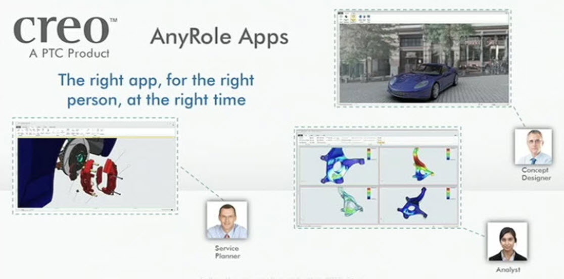
Figure 14: AnyRole Apps
First, let’s discuss the role of the Design Manager, an infrequent user of 3D CAD. However, he would like to preview the portfolio of the product line. This role specific app allows him to review the data, interrogate the data (cross section, interference analysis) communicate with the design team buy adding a note, and store this data and run specific reports within the enterprise PLM tool. See Figure 15.
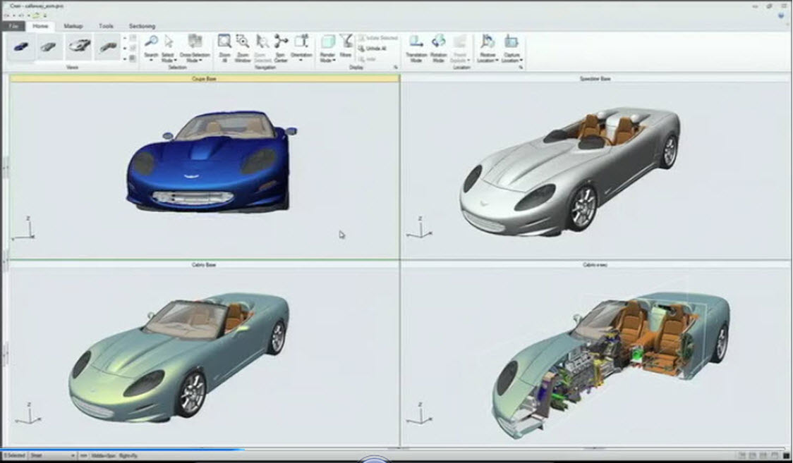
Figure 15: Design Manager App reviewing a portfolio of products
Second, let’s discuss the role of the Conceptual Designer/ Industrial Designer. He wants to be able to design relative to a 2D sketch, he wants surface creation tools for the form of the design, freely using sub-divisional surfacing, 3D co-pilot to pick and drag geometry around, and even some parametric modeling to mirror geometry, apply features like rounds, chamfers, etc. All of this in a purpose built app that is extremely easy and flexible to use. See Figure 16.
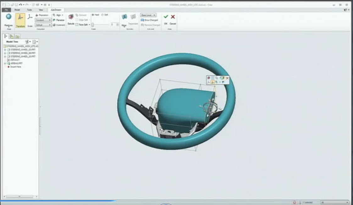
Figure 16: Conceptual Designer using sub-divisional surface modeling
Third, let’s discuss the role of the Analyst. He wants to work with the engineering data, simplify the engineering data. So in this app, we give direct editing tools to remove geometry easily regardless of the complexity or parent/child relationships. He then needs the tools to perform his FEA analysis, and then review the results of the analysis.
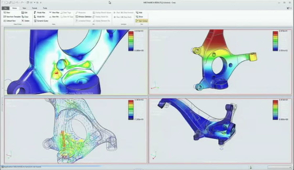
Figure 17: Analyst using direct editing tools to simplify geometry and run analysis
Fourth, let’s discuss the role of the Service Planner, Technical Writer. These individuals, like many in the product development process, are interested in deliverables from the CAD system. They want 3D exploded views, animations, complex concepts graphically to assemble, disassemble, and repair the products in the market. Also, this info can include callout for service BOM info as well. See Figure 18.
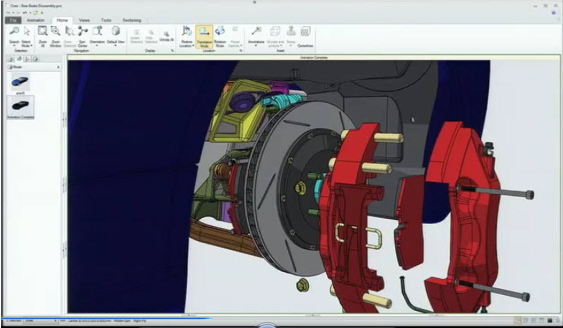
Figure 18: Service Planner making 3D exploded animations for disassembly
Fifth, let’s discuss the role of the 2D draftsman. He needs tools to create a 2D production drawing, no 3D tools required. Has the ability to create views, reference views, cross-hatching, mirroring, and creation of dimensioning all within a purpose built app. See Figure 19.
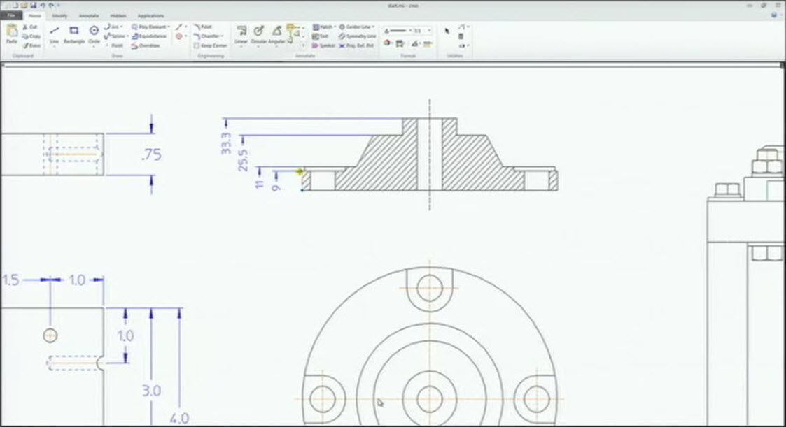
Figure 19: Drafter creating a 2D drawing
Sixth, let’s discuss the role of the manufacturing engineer. He needs tools to reuse engineering data, create, validate and optimize our tool paths. There will also be apps for mold design, progressive die design, and many others. See Figure 20.

Figure 20: Manufacturing Engineers leverage CAD data and machine parts
Seventh, let’s discuss the role of the sales and marketing. They need tools to reuse engineering data for renderings. There will also be apps for creating photorealistic renderings in a HDRI realistic environment with lights, materials, environmental effects. All within a very simple user interface of two tabs, six buttons. See Figure 21.
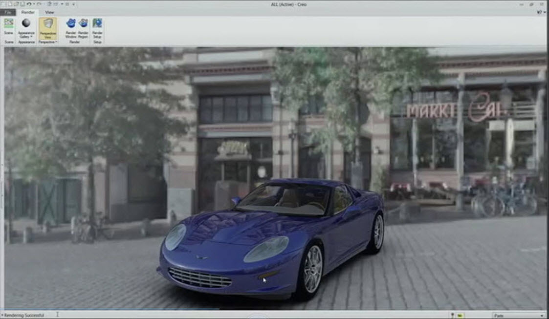
Figure 21: Marketing creating photorealistic images in simple app
Finally, let’s discuss the role of engineers. PTC has not forgotten our heritage of Pro/ENGINEER and will continue to provide the world-best parametric modeler. This app will have all of the power of a parametric modeler by editing a feature or parameter, and it updating throughout. All apps within Creo will have the end-to-end associativity, that a change made anywhere, updates everywhere.
These apps are not too big, not too small, but just the right size apps, for each role within the product development process. That will make the product development process a lot more inclusive. Some of the tools will come from PTC; however, many apps will come from 3rd party partners as well because Creo is an open system.
AnyMode Modeling
The second breakthrough technology is AnyMode Modeling. The critical point is that within the Creo suite of apps, data flows between the various modes – 2D, 3D, Assemblies, between various role-based apps, and between various paradigms of modeling methods – parametric and direct. That is accomplished by this new, underlying data model that allows the various apps to share data seamlessly.
There are fundamentally two major challenges addressed by AnyMode Modeling. The first challenge is moving data from a 2D environment to a 3D environment. With Creo, PTC will deliver a 2D, conceptual engineering environment. The conceptual work may start from scratch; it may start from taking a cross-section from a 3D model, or by building it off an existing drawing. This upfront conceptual work will typically be done in a 2D only dedicated environment. The conceptual engineering app will contain the initial 2D conceptual tools. It will provide the ability to sketch in 2D, to create your concepts, to explore ideas, and then gradually over time add intelligence (constraints, relationships, etc) to the design. Then, a user can take the 2D concept in 3D and use it as a basis for his 3D design. The fluency at going back and forth between the 2D and 3D conceptual design environments will make it easier than ever and maintain intelligence between the two modes. See Figure 22.
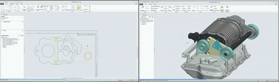
Figure 22: 2D to 3D conceptual design
The second major challenge addressed by AnyMode Modeling is moving between parametric to direct in the 3D world. Today, PTC has a direct modeler in CoCreate, and a parametric modeler in Pro/ENGINEER. However, if you bring data from the parametric modeler into a direct modeler, you will not be able to bring it back into parametric as it will lose its feature history. With Creo, a user will be able to grab a parametric model, simply select a set of geometry, not worry about parent/child relationships/design intent, and he will be able modify that geometry easily. In real time, he will be able to see his changes and how the geometry adapts. In this new app, you also be able to create geometry in a direct modeling approach. There also is no overhead like with a parametric modeler. No history tree, no regeneration, no roll-back. That model can now be saved and opened up in any of the Creo apps because it is stored on the common data model. So now when that saved model is opened in the parametric modeler, there is the ability to turn on an option to track changes. This works very similar to the way Microsoft apps track changes in a Microsoft Office document. The user then has the ability to accept or reject changes. Then all the parametric features have been completely preserved as well as all of the direct edit features are included. So when the model is open in the parametric app, the user sees all the features and the history maintained. When the model is open in the direct edit app, the user sees only the geometry. What is truly amazing is that all of the feature intelligence is maintained and editable. Also, the user can make edits to the direct features parametrically and have those changes update. This provides full round-trip modification in both a direct and parametric mode. It’s a powerful way to make changes and maintain intelligence in the model. See Figure 23.
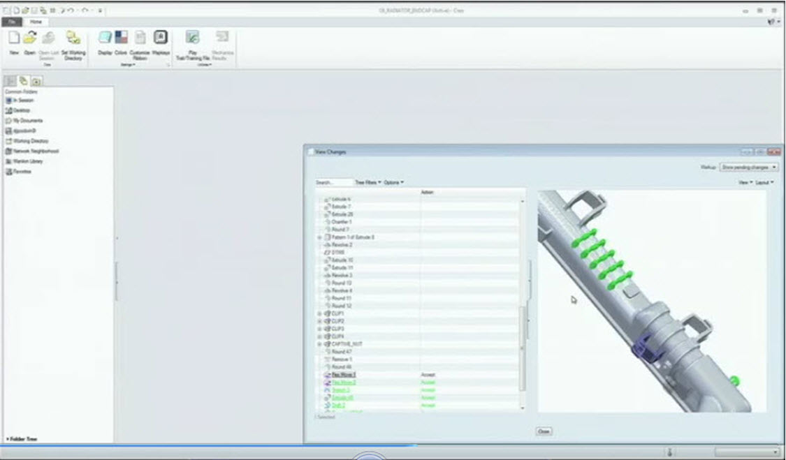
Figure 23: Tracking changes from direct edits to a parametric model
PTC is not just adding direct edit capabilities to Pro/ENGINEER like some CAD tools today. This is very limiting and often does not allow the user to work in just their app or mode of choice. This AnyMode Modeling technology is built on the most powerful geometry kernel on the market and now unleashed on direct modeling. These capabilities are provided in dedicated apps that work in either paradigm of 2D or 3D and direct or parametric with no loss of design intent or flexibility. This is really offered because of the underlying common data model between all apps.
AnyData Adoption
The third breakthrough technology is AnyData Adoption. We live in a multi-CAD world that is not going to change anytime soon. So what about CAD data that was created somewhere else – in some other CAD tool? How does that data move into Creo?
Fundamentally, Creo will allow the use and re-use of CAD data from external systems inside the Creo environment. This data can be visualized, edited, and maintained going forward in Creo. For instance, if they want to create a tool path, run an analysis, create some tech publishing information, all of those role based apps will work fine with data from an external CAD system. The data is adopted, brought into the Creo family.
The demonstration showcased Unigraphics data, CATIA data, and Pro/ENGINEER all assembled together. The assembly had interference and the user was able to make direct edits to the geometry and change it contour shape right within Creo. See Figures 24 & 25.
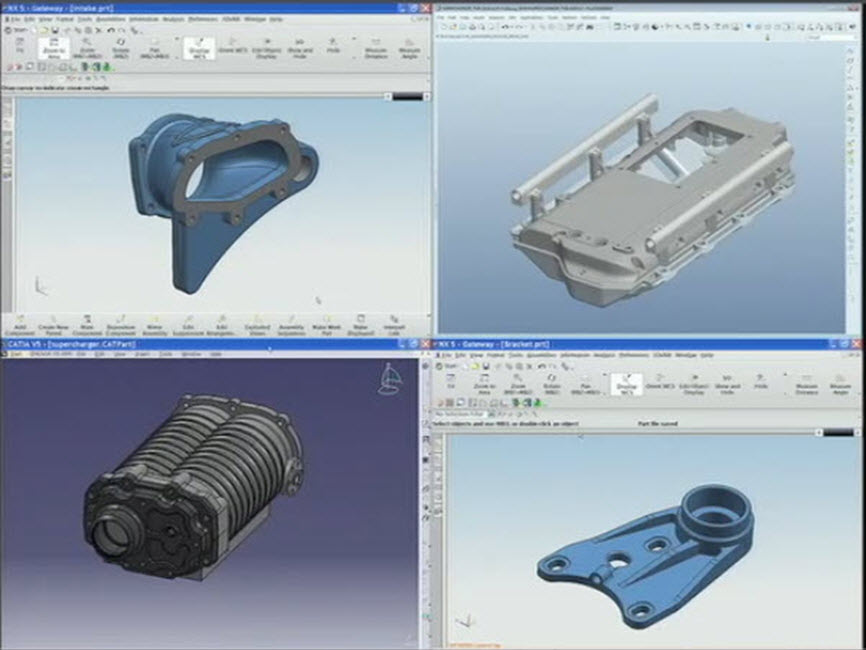
Figure 24: CAD Data brought in from CATIA, UG, and Pro/E
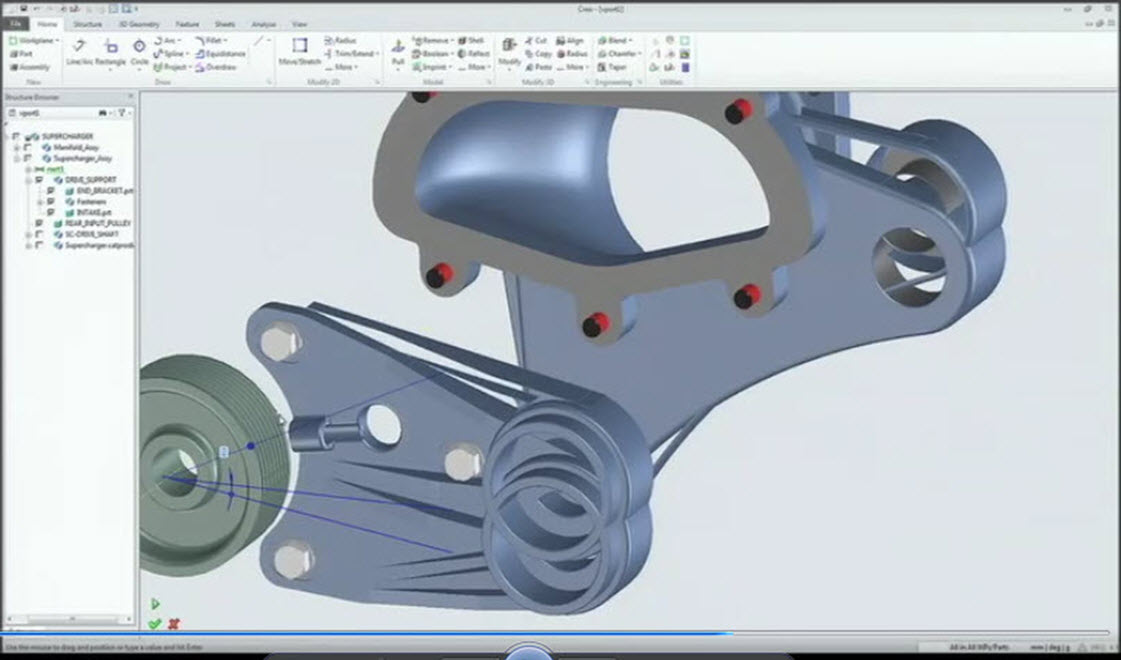
Figure 25: Making major direct edits to the non-native geometry
Companies have built up a tremendous amount of legacy data. How do companies maintain that going forward? Sometimes, the original tool that created the data is no longer available. With Creo, the user will be able to bring that data into Creo and maintain that data moving forward in a much more cost effective manner.
AnyBOM Assembly
The fourth and final breakthrough technology is AnyBOM (Bill of Material) Assembly. CAD systems have been great at modeling 3D models of parts. Then as a natural extension, these parts are arranged together into an assembly. This works well if you are building 1, 2, or 3 assemblies. But if you are starting to deal with configurable products that come in dozens, hundreds, even thousands of variants, how do you scale all that? The reality is you can’t get there today with the typical bottom up assembly approach. Often companies only model a few representative assemblies, and end up with problems on the manufacturing floor when never modeled configurations do not fit together, or do not meet the performance needs for cost, compliance, or weight.
Leveraging Windchill, as the configuration kernel, allows customers to configure their product by defining a platform of their products with a generic bill of materials with all of its variants. Windchill can manage huge complexity in the options/variants of BOM’s. However, what has been missing is the ability to move that information into the design environment to review, edit and analyze that information. So this is true top down assembly modeling from a bill of material, all the way down to a specific, serialized configuration where you can use any of the role-specific apps to perform actions on this specific configuration. This kind of integration between PLM and CAD has never been done before.
The generic structure can be defined in Windchill which includes all the options and variants. This data can be configured in the Creo configuration modeling app. It’s a purpose built app to allow a user to create configurations. If an option doesn’t exist, the user can search the PLM system and include it as an option to the configuration. Once these configuration options have been made, we can push these changes back to the PLM system. Also, the source CAD data is color coded to show where the original CAD data came from.
In the configuration modeler, the user can make a serial specific configuration, and then with a simple app switcher, the user can switch to a 3D visualization view, 3D parametric view, 3D direct view, manufacturing view, service view, render view, etc. So now, a user can quickly select and build a specific configuration and have it automatically generate a 3D viewable, a 3D CAD data for editing purposes or any other downstream deliverable need required. See Figure 26.
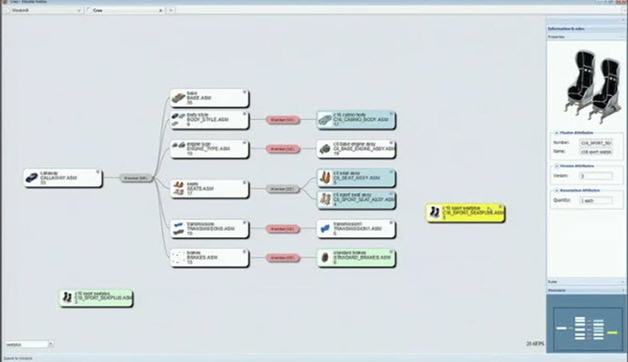
Figure 26: Configuration Modeler app
Product Roadmap for Creo
So when is Creo going to be delivered? The first seven Any Role apps are tentatively scheduled for summer 2011 in Creo 1.0. The apps will include a:
1) parametric modeling
2) direct modeling
3) structural simulation
4) conceptual engineering
5) schematics
6) 3D technical illustrations and
7) visualization
Creo 2.0 will follow in the fall 2011 to also include another app for configuration modeling. This will also coincide with a secondary release of Windchill 10.0 to support the connection of PLM to CAD with AnyBOM Assembly. A beta release is planned for spring of 2011 for customers. See Figure 27.
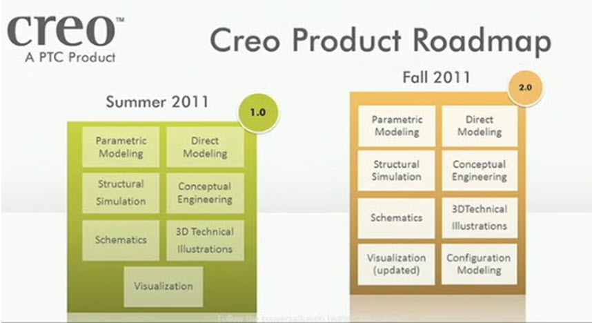
Figure 27: Tentative Creo Product Roadmap*
Marketing Campaign for Creo
Rob Gremley, Executive Vice President of Marketing, announced that on October 28, PTC launched the single, largest product marketing campaign in the history of PTC. PTC will be marketing throughout the social media sphere, in printed & web media, and thru social networking of Planet PTC Community. One of the best places to learn more about Creo is at PTC micro site: http://creo.ptc.com. Bookmark it, RSS it and it will evolve as more details about the product evolve. With the launch, PTC is also renaming our three flagship products of Pro/ENGINEER, CoCreate and ProductView to creo elements/pro, creo elements/direct and creo elements/view respectively. See Figure 28.

Figure 28: Rebranding of Pro/ENGINEER, CoCreate and ProductView
The Creo prefix is the connection to the future of the products. The suffix of /pro, /direct and /view is a connection to the present products. Creo is the vision for CAD for the next twenty years, but it also is a real product suite of tools that you can buy and use with confidence today. PTC 25,000 valued customers are already on the path to Creo. Both their data (in Pro/ENGINEER, CoCreate, and ProductView) and their business relationship are maintained.
Jim Heppelmann came to the stage for his closing comments. He said he has not seen this much energy and excitement in the CAD industry in twenty years. Within the company, everyone is talking about Creo, wants to be a part of it, and wants to see it succeed. PTC is not just shipping a next release of CAD. Instead it is tackling the four toughest problems faced by discrete manufactures today, and with a defined vision and four breakthrough technologies that no other vendor can provide. This ultimately will unlock the potential for creativity, teamwork, efficiency and value to help our customers reach and exceed their goals in product development.
This is an extremely exciting time to be both a PTC employee and customer. Our commitment to deliver some amazing technology to solve the toughest problems is something I want to be associated with. I personally am very excited to be part of the helping the company reach its vision and deliver on its promises to our customers. The excitement and comments from everyone I spoke to at the event were positive and everyone is hoping for PTC to turn their vision into reality in the coming months and years.
To watch a replay of the Creo Launch event, please go to: PTC - Creo - Event Replay: Unveiling of Creo. And to learn more about Creo, please go to: http://creo.ptc.com/.
You can read the Desktop Tip of the Month here also authored by Jon Jarvis and you can also read the Enterprise Product Focus of the Month here and the Enterprise Tip of the Month here authored by Bruce Hulse.
This thread is inactive and closed by the PTC Community Management Team. If you would like to provide a reply and re-open this thread, please notify the moderator and reference the thread. You may also use "Start a topic" button to ask a new question. Please be sure to include what version of the PTC product you are using so another community member knowledgeable about your version may be able to assist.
0 REPLIES 0


