Community Tip - Stay updated on what is happening on the PTC Community by subscribing to PTC Community Announcements. X
- Community
- Creo+ and Creo Parametric
- 3D Part & Assembly Design
- Re: Thin plate + contact
- Subscribe to RSS Feed
- Mark Topic as New
- Mark Topic as Read
- Float this Topic for Current User
- Bookmark
- Subscribe
- Mute
- Printer Friendly Page
Thin plate + contact
- Mark as New
- Bookmark
- Subscribe
- Mute
- Subscribe to RSS Feed
- Permalink
- Notify Moderator
Thin plate + contact
Hi all,
I use Creo 2.
I would analyze this assembly where we have two identical parts composed by a thin plate with 8 holes (for bolts that are simulated as fasteners) and a thin tube that is weld on the plate.
This two structure are assembled together with the bolts, they are constrained at the bottom and there is a bending moment at the top.
In the first test I have meshed all with shells and I have inserted a contact surface between the two plates; but the shells don't support the contact regions.
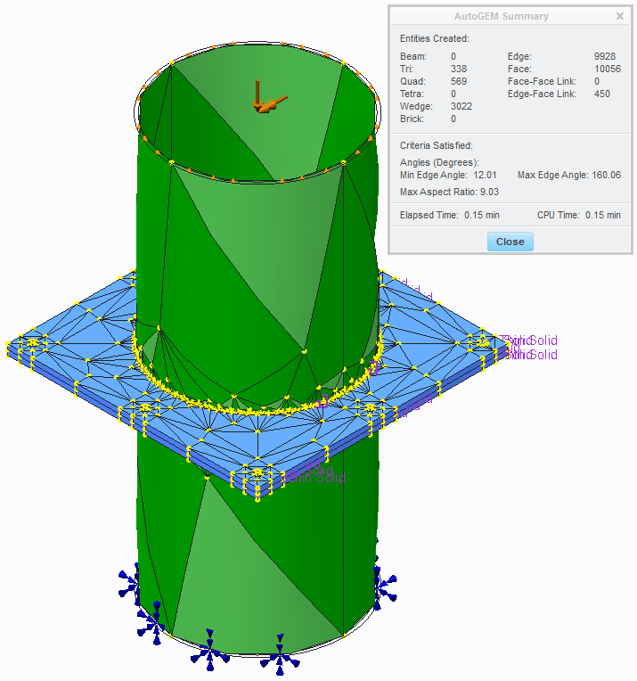
In the second I have meshed the plates with tetra and the tubes with shells; Creo has meshed but there was so much tetra, due the very thin plate (6 mm) that I suppose it should take many hours to converge...if it can...
In the third case I've tried to mesh the plates with the mapped mesh control, in an attempt to have a more regular mesh with few elements. But I'm not able to link this mapped mesh with the tube above the plate.
Any suggestions?
This thread is inactive and closed by the PTC Community Management Team. If you would like to provide a reply and re-open this thread, please notify the moderator and reference the thread. You may also use "Start a topic" button to ask a new question. Please be sure to include what version of the PTC product you are using so another community member knowledgeable about your version may be able to assist.
- Mark as New
- Bookmark
- Subscribe
- Mute
- Subscribe to RSS Feed
- Permalink
- Notify Moderator
You could use thin-solid elements, but I believe you can't use them in conjunction with the fastener tool; this means that you'd need to manually create your idealized fasteners. A key feature of thin solid elements is that the p-order on element edges through the thickness are limited; this helps reduce computational time but also means you mean apply the same restrictions as shell elements (essentially).

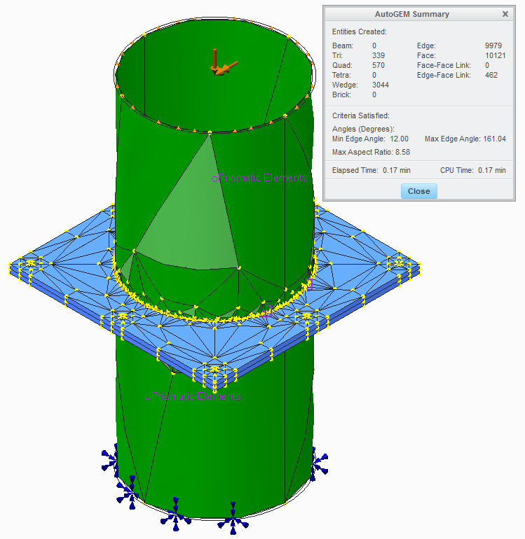
You could also use a prismatic mesh control to prevent the creation of tet elements in the plate. Since these are regular solid elements, you can use the fastener tool with them.

- Mark as New
- Bookmark
- Subscribe
- Mute
- Subscribe to RSS Feed
- Permalink
- Notify Moderator
Hi Shaun,
You could use thin-solid elements, but I believe you can't use them in conjunction with the fastener tool; this means that you'd need to manually create your idealized fasteners.
If I use thin elements (solid) I can't insert the contact surface between the two plates because the couple thin solid/contacts is not supported by the solver.
The same as I use shells/contacts.
I think it is due to the theory of thin elements treated like membranes here, if I remember well, you don't take in consideration the deformations in the verse orthogonal at the plate.
You could also use a prismatic mesh control to prevent the creation of tetra elements in the plate. Since these are regular solid elements, you can use the fastener tool with them.
I've tried before, in other assemblies, to use prismatic elements, but apart some simple cases, the mesher cannot create the mesh and it resorted to tetra elements.
Can you upload the assembly of your second photo?
Thanks
- Mark as New
- Bookmark
- Subscribe
- Mute
- Subscribe to RSS Feed
- Permalink
- Notify Moderator
I played around with your model and it looks like neither will work; both thin-solid elements and prismatic elements cause issues with pairing the linked elements (which is due to the contact interface). I'll have to play with it some more when I have more time, but as of now it looks like a standard tet mesh is your only option.
- Mark as New
- Bookmark
- Subscribe
- Mute
- Subscribe to RSS Feed
- Permalink
- Notify Moderator
For now the best compromise that I have found is by doing a volume region on the tube near the plate so as "divide the tube in two parts", applying thin elements on the upper part of tube.
So it works, but maybe it isn't the best way.
Other question is that, for example in the files that now I upload, the solver says you that the deformation is high and a LDA (Large deformation analysis) is recommended. But fastener, shell, solid screws with preload or heat load era not supported...
I specify that the structures that at work I analyze, like these, are already made (I can't modify them for improve the design) and the load on these are imposed.
- Mark as New
- Bookmark
- Subscribe
- Mute
- Subscribe to RSS Feed
- Permalink
- Notify Moderator
Hello.
My 2 cents:
I just had a try and it took 40 minutes to solve the analysis with shell pair idealization (1536 elements) and 20 minutes without idealization (5342 elements) .
I have first removed the mapped mesh control, deleted surface regions, assigned material, added infinite friction to the interface, enabled contacts in the analysis definition and run the analysis with Quick check convergence method.
- Mark as New
- Bookmark
- Subscribe
- Mute
- Subscribe to RSS Feed
- Permalink
- Notify Moderator
I've assigned the material in the Model Properties . For this there are not the material assignment in the Simulate enviroment.
- Mark as New
- Bookmark
- Subscribe
- Mute
- Subscribe to RSS Feed
- Permalink
- Notify Moderator
"I just had a try and it took 40 minutes to solve the analysis with shell pair idealization (1536 elements) and 20 minutes without idealization (5342 elements) ."
This is due to the constraint equations that Mechanica needs to create to link the shell elements to the solid elements (those pink lines you see between the two different element types). Multipoint constraint equations are very expensive from a computational standpoint, but they only become an issue if you have a significant number of them. Given the fine mesh level at the interface between solid and shell elements, it's not surprising that the shell element model takes longer to solve than the solid element model.
- Mark as New
- Bookmark
- Subscribe
- Mute
- Subscribe to RSS Feed
- Permalink
- Notify Moderator
Any suggestions to handle the issue of thin plates with contact region (the best manner) ?
- Mark as New
- Bookmark
- Subscribe
- Mute
- Subscribe to RSS Feed
- Permalink
- Notify Moderator
My suggestion...
-Use symmetry
-Bolts modeled as beams w. rigid links at endpoints
-Bolt preload modeled w temp. load
-shell elements in pipes
-solid elements in plates
-surface-surface contact interface
- Mark as New
- Bookmark
- Subscribe
- Mute
- Subscribe to RSS Feed
- Permalink
- Notify Moderator
Thanks Mats,
some questions:
- the horizontal plates do you have mesh them with tetra elements? Or else?
- Bolts modeled as beams with rigid links at end points gives you some benefits more than the fasteners features?
- Mark as New
- Bookmark
- Subscribe
- Mute
- Subscribe to RSS Feed
- Permalink
- Notify Moderator
In this case I used tetra-elements with default settings. Of course mapped mesh/refined mesh would give more accurate results and/or faster convergence, but I didn't bother to do that in this case.
I prefer using beams + temperature load to model bolts.I find the pre-defined fasteners limited; they don't always work, depending on geometry, and they work a bit like "black-box models" - I don't feel I understand exactly what they do. Using beams + temperature load I have full control. The drawback is that you need to run the pre-load analysis a few times to get the correct pre-load. I typically set the material's coefficient of thermal expansion to zero for most of the structure, and for example to 0.001 for the bolt material. With a temp. load of -1, then the bolts will contract. You can tune either the temp-load or the bolt material's coeff. of thermal expansion to get the desired bolt pre-load. And I can track how the bolt force changes as I apply external load to the structure, aswell as the force in the clamped parts.
I should also mention that in this case I have not used "half-circle" bolt cross sections for the bolts on the symmetry plane. So those bolts are too stiff./M
- Mark as New
- Bookmark
- Subscribe
- Mute
- Subscribe to RSS Feed
- Permalink
- Notify Moderator
"...and they work a bit like "black-box models" - I don't feel I understand exactly what they do..."
In case you're interested Mats, here's a pdf that gives a basic overview of what is going on behind the scenes. You'll notice that this is for WF 2.0, at which point the "fasteners" couldn't carry bending moments. However, in Creo (and maybe even earlier...I forgot when) the tool was modified to capture bending moment effects. PTC did some research on determining the off-diagonal terms for an advanced spring element to mimic the stiffness matrix of a beam element if I recall correctly.
- Mark as New
- Bookmark
- Subscribe
- Mute
- Subscribe to RSS Feed
- Permalink
- Notify Moderator
So it seems that these cursed plates are intended to be meshed by tetra elements...
Or does someone know some special technique to do mesh between parts with the shape a little complicated?
In my experience "prismatic elements" works only on prismatic solids without holes; "mapped mesh" needs guide lines (I have done volume regions), so much time and it don't work if the entire assembly is not mesh with that tool.
- Mark as New
- Bookmark
- Subscribe
- Mute
- Subscribe to RSS Feed
- Permalink
- Notify Moderator
The utilization of prismatic elements is not possible if you want to use the fasteners to let the plates in contact. It seems that only tetra elements can "support" fasteners.
You can utilize prismatic elements with solid bolts preloaded with thermal load or the creo 2 preload feature but, if you want to maintain the contact surface between plates, you must remove the flag on the voice "Generate compatible mesh". This also means that, not having the compatibility between the nodes on the interface, probably it will require major time to get to convergence (maybe, I'm not sure 100%).
In all of this, I don't understand yet how to use the feature "Mapped Mesh" properly if not on simple single parts or assembly with few elements, always simple.


