

Unfolding a FPC copper pattern in Creo 2.0 (M120)
Hello
I'm an antenna designer and I'm currently working on an antenna design on a Flexible Printed Circuit Board (FPC). I use Creo to model my antenna design in 3D, which I can then export to an EM simulator.
The FPC consists of a substrate and a copper pattern. The substrate is an unbroken solid and I can unfold that part with no issues. I can also unfold my copper pattern (the antenna) as long as I keep it as an unbroken solid. However, some antenna designs uses components whereby the antenna pattern is no longer an unbroken solid and I can't not unfold it anymore. See example below;
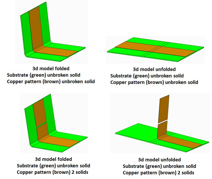
The substrate and the copper pattern are modeled in 2 different parts and converted to sheetmetal after I thicken the surface.
I know that sheetmetals normally are unbroken solids and this is probably why I can't unfold my antenna design. But is there another way I can do this in Creo ?
Thanks in advance,
Simon
This thread is inactive and closed by the PTC Community Management Team. If you would like to provide a reply and re-open this thread, please notify the moderator and reference the thread. You may also use "Start a topic" button to ask a new question. Please be sure to include what version of the PTC product you are using so another community member knowledgeable about your version may be able to assist.