
Turn on suggestions
Auto-suggest helps you quickly narrow down your search results by suggesting possible matches as you type.
Showing results for
Please log in to access translation
Turn on suggestions
Auto-suggest helps you quickly narrow down your search results by suggesting possible matches as you type.
Showing results for
- Community
- Creo+ and Creo Parametric
- 3D Part & Assembly Design
- Use top assembly dimensions/parameters in a sub-as...
Translate the entire conversation x
Please log in to access translation
Options
- Subscribe to RSS Feed
- Mark Topic as New
- Mark Topic as Read
- Float this Topic for Current User
- Bookmark
- Subscribe
- Mute
- Printer Friendly Page
Use top assembly dimensions/parameters in a sub-assembly/part
Oct 17, 2012
01:23 PM
- Mark as New
- Bookmark
- Subscribe
- Mute
- Subscribe to RSS Feed
- Permalink
- Notify Moderator
Please log in to access translation
Oct 17, 2012
01:23 PM
Use top assembly dimensions/parameters in a sub-assembly/part
I have a top assembly of a set of steel or aluminum stairs that has a parameter for the stair tread depth (from front to back, when ascending the stairs). I have a sub-assembly of each step that has a piece of steel angle in the front, one in the back, and a stair tread resting between the two. I would like to be able to change the tread_depth parameter in the top assembly and have it change the distance between steel angles and coincidentally, the stair tread depth in the sub-assembly.
Is there a way to reference a top assembly parameter in the sub-assembly? I am familiar with relations, but I'm not sure if there's a different format for referencing a d-value (dimension) in a sub-assembly.
Thanks in advance
This thread is inactive and closed by the PTC Community Management Team. If you would like to provide a reply and re-open this thread, please notify the moderator and reference the thread. You may also use "Start a topic" button to ask a new question. Please be sure to include what version of the PTC product you are using so another community member knowledgeable about your version may be able to assist.
Solved! Go to Solution.
Labels:
- Labels:
-
2D Drawing
ACCEPTED SOLUTION
Accepted Solutions
Oct 17, 2012
05:23 PM
- Mark as New
- Bookmark
- Subscribe
- Mute
- Subscribe to RSS Feed
- Permalink
- Notify Moderator
Please log in to access translation
Oct 17, 2012
05:23 PM
Hi Chris...
Sorry - I thought I saw on a tag that you were on Creo 2. Ah well.
Simple answer... set the relations in your parts and subassemblies from the top level assembly relations window. Pro/E will automatically add the correct Component ID to the dimension.
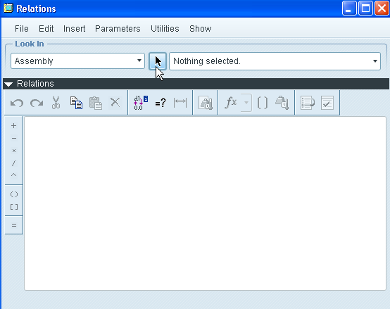
Get to your top assembly. Name your dimensions however you wish. Edit the dimensions of your parts and subassemblies using relations... but do it at the top assembly. Go to the relations window and select the arrow icon (shown below)... next pick the part or subassembly containing the dimension you wish to change.
Once you've selected the appropriate part or subassembly, pick a feature or component and you'll see the dimensions pop up. You'll notice they no longer appear as simply "d1", "d4", "d18", etc... but they have a colon and a number appended as a suffix.Click any dimension to add it to your relations window.
For example, instead of "d14", you'll see "d14:5" (the number after the colon will vary). This is the Component Id of the model. If you want to look further, you can turn on Feature ID in the Model Tree and at the assembly level you should see the Component Id is the same number that Pro/E is appending to your dimensions.
So in your case, if the dimension you're trying to vary is deep down in a part:
- open your relations editor, pick the arrowhead
- select the part you wish to grab a dimension from
- pick the feature to show the various dimensions
- select the desired dimension - the dimension appears (complete with component id) in the relations editor
- Complete the relations as desired...
If the width of your tread is driven by "TREAD_WIDTH" minus 1/2" for clearance, then your relation might be: d14:5 = TREAD_WIDTH - .50
When you exit the relations editor and regenerate, the model wil update.
Although I should reiterate ... this is not the best way to accomplish this goal. You should really try using top level design techniques or, at the very minimum, a master model to handle this. There's documentation on the web for both techniques... or I can demonstrate (although I am getting a bit busy today and I may not get back to it in time).
Thanks!
-Brian
4 REPLIES 4
Oct 17, 2012
03:38 PM
- Mark as New
- Bookmark
- Subscribe
- Mute
- Subscribe to RSS Feed
- Permalink
- Notify Moderator
Please log in to access translation
Oct 17, 2012
03:38 PM
Hi Chris...
I created a sample set of parts with a sample step subassembly. I then assembled each step and used a pattern to make a repeating set. Here's a picture...
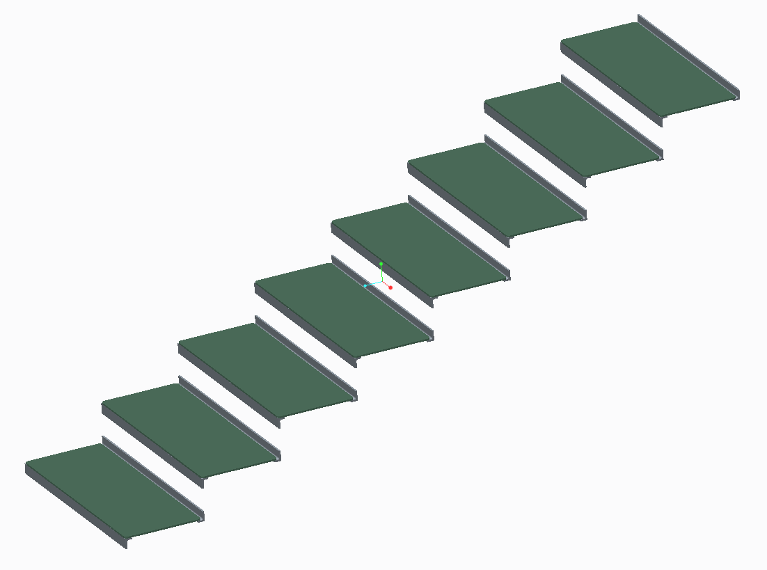
To modify the stair pattern, open the top level assembly (called step_assy.asm). Modify the PATTERN and you'll see both the height and width dimensions. When you modify the width dimension, that number ripples down into the subassembly and parts. The stair tread will adjust accordingly... and so will the dimension between the front and back angles supporting the tread. This is what you asked for... so this is what I modeled.
However... this is a really poor way to go about modeling this staircase. Having assembly dimensions that drive part dimensions is a bad way to go. A better way would be to leverage a top-down design process with a skeleton model. The skeleton would hold all pertinent information about your staircase including tread height, depth, etc. This data would then be referenced in the tread part and in the subassemblies.
There are several ways to go about achieving what you've asked for. All of them are better than what I've modeled here. If you're interested, I can remodel this using a top down design scheme with a skeleton. I think you'll see the difference immediately.
Take a look at the attached models and see if they make sense to you. There are relations driving the tread width and the subassembly width between the angles. Look at the relations in those models and you'll see how I did it.
Thanks!
-Brian
Oct 17, 2012
04:13 PM
- Mark as New
- Bookmark
- Subscribe
- Mute
- Subscribe to RSS Feed
- Permalink
- Notify Moderator
Please log in to access translation
Oct 17, 2012
04:13 PM
Brian,
Will I be able to see your relations in a .neu file? I'm currently working in Creo 1.0 and was unable to open your model.
I've attached mine, I solved some of the problems, but still am wondering about my original question. If you look in my parameters, I have one called TREAD_DEPTH. I was wondering if I could write a relation to the effect of dXX (actual tread depth) = tread_depth - 0.25 to drive the ACTUAL stair tread to be 1/4" less than the desired stair run so that it would fit within the angles set apart by TREAD_DEPTH. I was assuming there might be some extra notation I could put in front of "dXX" in my top level assembly that might say to Creo that "this is the dXX dimension of part:'stair_tread.'"
I believe, as of now, I have 4 parameters that change various dimensions on the model: TREAD_DEPTH, DOOR_WID, LANDING_HEIGHT, LANDING_DEPTH_MIN. Feel free to change those. I added some relation comments to make it easier for you to understand.
Thanks for the help already,
Chris
Oct 17, 2012
05:23 PM
- Mark as New
- Bookmark
- Subscribe
- Mute
- Subscribe to RSS Feed
- Permalink
- Notify Moderator
Please log in to access translation
Oct 17, 2012
05:23 PM
Hi Chris...
Sorry - I thought I saw on a tag that you were on Creo 2. Ah well.
Simple answer... set the relations in your parts and subassemblies from the top level assembly relations window. Pro/E will automatically add the correct Component ID to the dimension.
Get to your top assembly. Name your dimensions however you wish. Edit the dimensions of your parts and subassemblies using relations... but do it at the top assembly. Go to the relations window and select the arrow icon (shown below)... next pick the part or subassembly containing the dimension you wish to change.
Once you've selected the appropriate part or subassembly, pick a feature or component and you'll see the dimensions pop up. You'll notice they no longer appear as simply "d1", "d4", "d18", etc... but they have a colon and a number appended as a suffix.Click any dimension to add it to your relations window.
For example, instead of "d14", you'll see "d14:5" (the number after the colon will vary). This is the Component Id of the model. If you want to look further, you can turn on Feature ID in the Model Tree and at the assembly level you should see the Component Id is the same number that Pro/E is appending to your dimensions.
So in your case, if the dimension you're trying to vary is deep down in a part:
- open your relations editor, pick the arrowhead
- select the part you wish to grab a dimension from
- pick the feature to show the various dimensions
- select the desired dimension - the dimension appears (complete with component id) in the relations editor
- Complete the relations as desired...
If the width of your tread is driven by "TREAD_WIDTH" minus 1/2" for clearance, then your relation might be: d14:5 = TREAD_WIDTH - .50
When you exit the relations editor and regenerate, the model wil update.
Although I should reiterate ... this is not the best way to accomplish this goal. You should really try using top level design techniques or, at the very minimum, a master model to handle this. There's documentation on the web for both techniques... or I can demonstrate (although I am getting a bit busy today and I may not get back to it in time).
Thanks!
-Brian
Oct 18, 2012
08:10 AM
- Mark as New
- Bookmark
- Subscribe
- Mute
- Subscribe to RSS Feed
- Permalink
- Notify Moderator
Please log in to access translation
Oct 18, 2012
08:10 AM
Brian,
Thanks, that's exactly what I was referring to. I'll have to check out the top-down tutorials. I've basically had to teach myself as far as relations go so I haven't been shown the correct way to go about doing it. I'm assuming it may help me avoid circular references (which I tend to have a really hard time solving) and such. Would this not be the best way to do this stair model if it's a standard model that I'll copy and edit for each of our jobs?
Thanks again
Chris


