

User Defined Features in Creo Elements Pro 5.0
You can read the Desktop Tip of the Month here also authored by Ryan Butcher and you can also read the Enterprise Product Focus of the Month here and the Enterprise Tip of the Month here authored by Brian Muttonen.
| PTC Technical Specialists Newsletter - February 2011 |
Product Focus : User Defined Features in Creo Elements Pro 5.0 |
|---|
There have been significant enhancements to User-Defined Features in Creo Elements Pro 5.0
A User-Defined Feature (UDF) consists of selected features, all their associated dimensions, any relations between the selected features, and a list of references for placing the UDF on a part. User-defined features can be subordinate or standalone. The UDF dialog box provides a running status of these UDF elements during UDF creation and modification.
There are 2 types of User-Defined Feature that can be created: Subordinate and Stand Alone.
Subordinate UDFs
A subordinate UDF gets its values directly from the original model at run time, so the original model must be present for the subordinate UDF to function. If you make any changes to the dimension values in the original model, they are automatically reflected in the UDF.
A model can have more than one subordinate UDF associated with it. Items in the family table of a subordinate UDF show the identifiers and symbols from the original model.
Standalone UDFs
A standalone UDF copies all the original model information into the UDF file. Because of this, a standalone UDF requires more storage space than a subordinate UDF. If you make any changes to the reference model, they are not reflected in the UDF.
When you create a standalone UDF, you have the option of creating a reference part by copying the original part from which the UDF is derived. The reference part has the same name as the UDF, with the extension _gp. For example, if you name a UDF radial_holes, the reference part is named radial_holes_gp.prt. A reference part displays UDF references and elements through the original features.
UDF Placement Using an On-Surface Coordinate System
One new capability in Creo Elements Pro 5.0 is constructing the UDF with an on-surface coordinate system. Then the placement of the UDF is completed very easily with a single pick and locating its position on the surface.
In order to use this type of UDF, you must construct the UDF in one of the two following ways:
- The on-surface coordinate system must be the first feature of the UDF.
- Any type of coordinate system must be the only external reference of the UDF, and all other references must be internal references.
The coordinate system serves both as an origin and a reference point for the UDF. It can be compared to a pin holding an add-on in place on the model surface by its axis.
When you create the UDF, the on-surface coordinate system must be the first defined feature. The placement point that you choose for the coordinate system is the placement point for the UDF on the model. If you do not place the UDF first, it is treated like any other feature, in which case the references of the coordinate system are listed in the Placement tab of the User Defined Feature Placement dialog box.
To Place a UDF Where the First Feature Is an On-Surface Coordinate System
- Create a UDF with a coordinate system as the first feature.
- With a target model open, click Insert ▶ User-Defined Feature. The Open dialog box opens.
- Select the created UDF group file and click Open. The Insert User-Defined Feature dialog box opens.
- Click OK. The User Defined Feature Placement dialog box opens to the Placement tab and the UDF preview appears.
- Define the Placement references:
- When the UDF has an on-surface coordinate system as the first feature, ON SURFACE CSYS, appears first in the References of Original Features list.
- Select ON SURFACE CSYS. The layout on the right side of Placement tab changes to a layout similar to the on-surface coordinate system dialog box.
- When the UDF has an on-surface coordinate system as the first feature, ON SURFACE CSYS, appears first in the References of Original Features list.
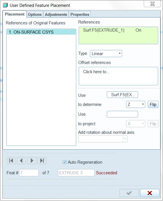
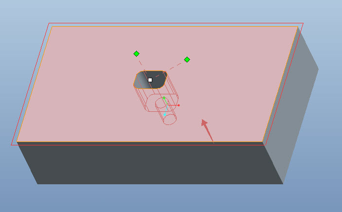
Select a plane or a surface to place the coordinate system reference in the Reference Surface box. A preview image of the UDF with coordinate system drag handles appears on the model.
Note
- If the UDF has no reference model, the preview displays only the on-surface coordinate system.
- If the UDF has reference model, the UDF preview contains geometry.
- If the UDF requires references other than the ones that define the on-surface coordinate system, the initial geometry preview is displayed. It is a copy of the UDF geometry in the reference model. This preview is referred to as an “unattached preview.”
- If there are no other references or all required references are defined, a solid “attached preview” appears with the UDF features highlighted.
c. Specify the offset references in the References box and use the drag handles to position the UDF. The coordinate system offset type can be Linear, Radial, or Diameter.
d. If necessary, modify the axes of the coordinate system location. The second axis direction sets the normal direction. Leave the first axis direction in the same direction as the placement surface normal.
Note
The axis letters are based on the original coordinate system feature.
e. If there are references other than the on-surface coordinate system in the References of Original Features list, specify them.
6. In the Options tab specify the following options:
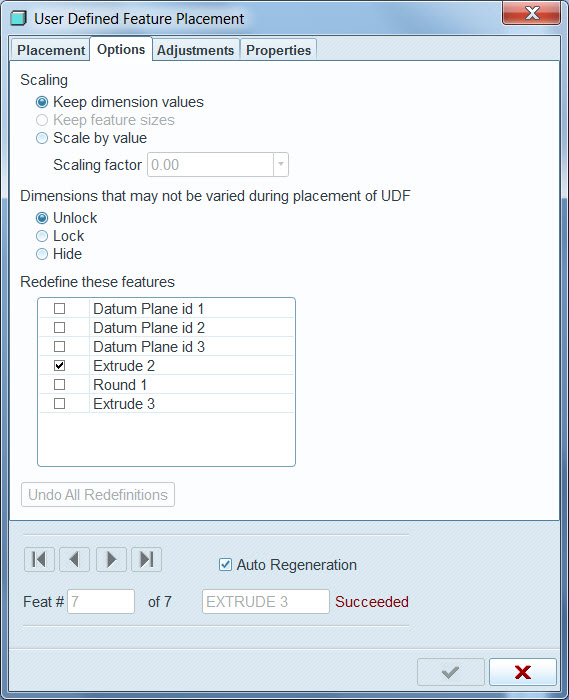
- Specify the placement scale by selecting one of the following options:
- Keep dimension values (default)
- Keep feature sizes
- Scale by value
- Keep dimension values (default)
- Specify how nonvariable dimensions are treated by selecting one of the following options:
- Unlock
- Lock
- Hide
- Unlock
- Add or remove features from the Redefine these features list to specify which features will be redefined during UDF placement. Features with variable elements are checked for redefinition by default.
- To remove all the redefinitions of the features carried out during UDF placement, select Undo All Redefinitions.
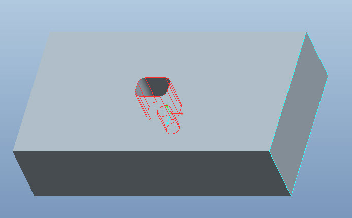
7. Click  . All UDF features regenerate and the User Defined Feature Placement dialog closes.
To find out more about Creo Element Pro 5.0’s User Defined Features visit our Website.
You can read the Desktop Tip of the Month here also authored by Ryan Butcher and you can also read the Enterprise Product Focus of the Month here and the Enterprise Tip of the Month here authored by Brian Muttonen.
This thread is inactive and closed by the PTC Community Management Team. If you would like to provide a reply and re-open this thread, please notify the moderator and reference the thread. You may also use "Start a topic" button to ask a new question. Please be sure to include what version of the PTC product you are using so another community member knowledgeable about your version may be able to assist.