Community Tip - Visit the PTCooler (the community lounge) to get to know your fellow community members and check out some of Dale's Friday Humor posts! X
- Community
- Creo+ and Creo Parametric
- 3D Part & Assembly Design
- Re: Using Area Driven Relation to Control Dimensio...
- Subscribe to RSS Feed
- Mark Topic as New
- Mark Topic as Read
- Float this Topic for Current User
- Bookmark
- Subscribe
- Mute
- Printer Friendly Page
Using Area Driven Relation to Control Dimension
- Mark as New
- Bookmark
- Subscribe
- Mute
- Subscribe to RSS Feed
- Permalink
- Notify Moderator
Using Area Driven Relation to Control Dimension
I am wondering if there is a way to control a dimension such that the area of the sketch will be a given value. What I am trying to do is control one sketch based on a height diemsion and the area of a different sketch. I have one sketch that I modify. Then a second sketch that has locked dimensions besides height is meant to be 2 times the area and I currently just modify height until I get it to be what I want it to be. I am trying to automate that process,
Thanks,
Brad
This thread is inactive and closed by the PTC Community Management Team. If you would like to provide a reply and re-open this thread, please notify the moderator and reference the thread. You may also use "Start a topic" button to ask a new question. Please be sure to include what version of the PTC product you are using so another community member knowledgeable about your version may be able to assist.
- Labels:
-
2D Drawing
- Mark as New
- Bookmark
- Subscribe
- Mute
- Subscribe to RSS Feed
- Permalink
- Notify Moderator
There is a way to present sketch perimeter in relation, but imo no way to directly control close loop area.
What you could do is create flat surface from first sketch (hide it if you do not need it), measure surface area of this surface by Analysis feature, do the same for the second sketch.
Add Optimization/Feasibility feature that will put SURF2 as a function of SURF1, and define "variable dimension" the one that can be driven in the dependent sketch.
Surely for simpler shapes you can manage by just relations that use geometrical knowledge, but for complicated sketches with no clear surface area formula you might need optimization.
- Mark as New
- Bookmark
- Subscribe
- Mute
- Subscribe to RSS Feed
- Permalink
- Notify Moderator
I have tried the optimization but I am unsure how to set it up so that it optimizes to the area of the first surface. The optimization seems to only allow for a min and max to be calculated.
Any ideas?
Thanks
- Mark as New
- Bookmark
- Subscribe
- Mute
- Subscribe to RSS Feed
- Permalink
- Notify Moderator
Sure, here you go :
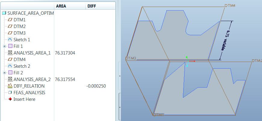
- have 2 surfaces SURF1 & SURF2 each one represents close sketch (given sketch has no area / parameter)
- AREA is AF1 (Analysis feature 1) parameter measuring SURF1. Another AREA is AF2 parameter measuring SURF2.
- Goal : get AREA (from AF2) = AREA (from AF1) (variable – dimension of SKETCH2).
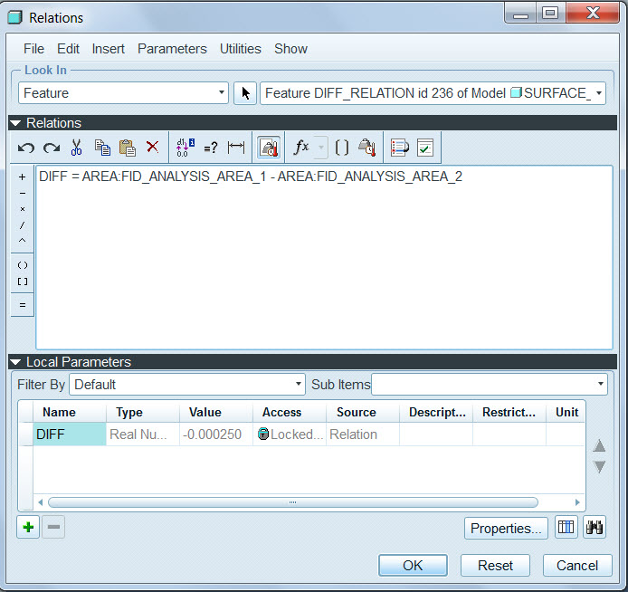
- Add 3rd analysis feature (AF3) of Relation type. Add DIFF parameter there with relation : DIFF = AREA:AF1 - AREA:AF2 (with proper syntax, with your correct IDs)
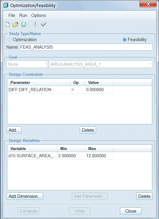
- In FEAS feature (select FEASIBILITY - not Optimization) set goal as DIFF = 0.
You will see - it works like a charm.I would attach a sample part if I knew how to attach here.
- Mark as New
- Bookmark
- Subscribe
- Mute
- Subscribe to RSS Feed
- Permalink
- Notify Moderator
Hmmm, I'll have to try this, thanks Vladimir!
- Mark as New
- Bookmark
- Subscribe
- Mute
- Subscribe to RSS Feed
- Permalink
- Notify Moderator
well, finally found how to attach the part
- Mark as New
- Bookmark
- Subscribe
- Mute
- Subscribe to RSS Feed
- Permalink
- Notify Moderator
In your part I am unable to see the relations parameters or the the feasibility study.
Any idea why this would be?
I am trying to set it up formy part and I cannot seem to get it to work.
Thanks
- Mark as New
- Bookmark
- Subscribe
- Mute
- Subscribe to RSS Feed
- Permalink
- Notify Moderator
Hey,
I have attached the incomplete version of the part - attaching the right one now.
- ANALYSIS_AREA_1 and ANALYSIS_AREA_2 measure sketch areas and output parameter "AREA"
- Analysis feature "DIFF_RELATION" has relation :
"DIFF = AREA:FID_ANALYSIS_AREA_1 - AREA:FID_ANALYSIS_AREA_2"
Feasibility feature FEAS_ANALYSIS sets DIFF to strive to ZERO.


- Mark as New
- Bookmark
- Subscribe
- Mute
- Subscribe to RSS Feed
- Permalink
- Notify Moderator
I got the first side to work but not I cannot get the second side of it to work. The issue that I am having is that the it will not allow me to save the feasibility study as a feature.
Any ideas?
- Mark as New
- Bookmark
- Subscribe
- Mute
- Subscribe to RSS Feed
- Permalink
- Notify Moderator
Run "compute" first - then this green "V" turns available.
Also note that Creo allows only one OPT / FEAS feature per model.
- Mark as New
- Bookmark
- Subscribe
- Mute
- Subscribe to RSS Feed
- Permalink
- Notify Moderator
Well the fact that they only allow one per model explains why I am having the issue. Any idea why they do this?
- Mark as New
- Bookmark
- Subscribe
- Mute
- Subscribe to RSS Feed
- Permalink
- Notify Moderator
Why would you need more than one ? You can add more than a single parameter goal to FEAS feature, as well as more than one variable dim (though I would not suggest having more than 2 in each section).
Allowing 2 or more FEAS / OPTM features will scramble regeneration looping process, that should be driven from a single place in order to converge.
- Mark as New
- Bookmark
- Subscribe
- Mute
- Subscribe to RSS Feed
- Permalink
- Notify Moderator
A picture of these areas would work wonders for trying to help....just sayin'..... ![]()
I sussessfully used a formula to constantly vary the cross-sectional area of a VSS (with a graph) while it transitioned from a 6" dia circle to an ellipse, and back to a circle of 5" dia.
Perhaps if it's an irregular shape, break it up into smaller shapes that ARE easily solved with a formula and use relations to control it all?
- Mark as New
- Bookmark
- Subscribe
- Mute
- Subscribe to RSS Feed
- Permalink
- Notify Moderator
The slot area is found using the analysis tool. The area of each side of the end turn needs to be equal to 6 times the area of the slot. I want to creo to automatically calculate the height of each end turn in order to be equal to the 6 times the slot area. The slot area calculation is shown below. The End Turn sketch is shown below that.
Let me know if you have any ideas of how to do this.
Thanks
- Mark as New
- Bookmark
- Subscribe
- Mute
- Subscribe to RSS Feed
- Permalink
- Notify Moderator
MUCH better. How accurate does it have to be? By "end turn", you mean removing material? ![]()
- Mark as New
- Bookmark
- Subscribe
- Mute
- Subscribe to RSS Feed
- Permalink
- Notify Moderator
I prefer it to be right on or atleast within a few square mm. The end turns add material. This is a model of the windings for an electric motor. The final component looks like this. The end turns are solid revolves on both ends to the slots.


