Community Tip - Want the oppurtunity to discuss enhancements to PTC products? Join a working group! X
- Community
- Creo+ and Creo Parametric
- 3D Part & Assembly Design
- Re: Variable Round
- Subscribe to RSS Feed
- Mark Topic as New
- Mark Topic as Read
- Float this Topic for Current User
- Bookmark
- Subscribe
- Mute
- Printer Friendly Page
Variable Round
- Mark as New
- Bookmark
- Subscribe
- Mute
- Subscribe to RSS Feed
- Permalink
- Notify Moderator
Variable Round
Morning All
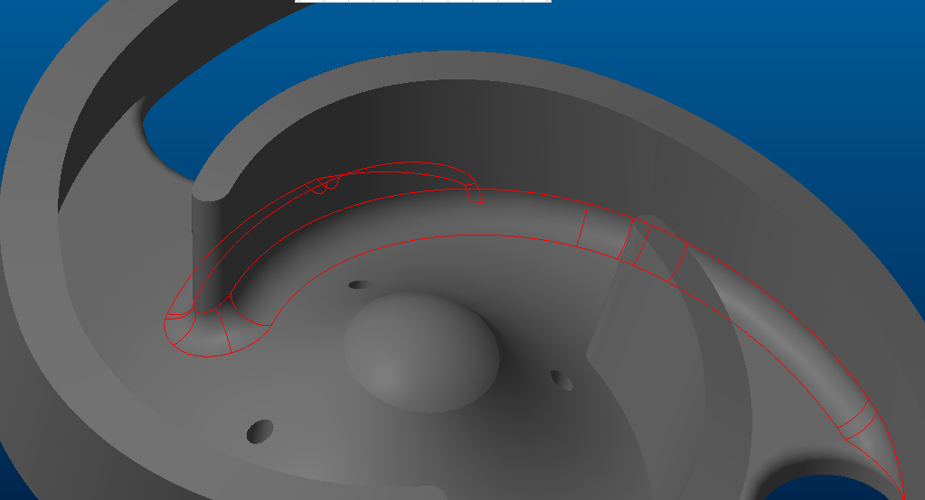
Been trying to get a 12 mm round on the attached drawing. Tried the surface to surface and even this won't work. any experts care to point me in the right direction?
Many Thanks.
Solved! Go to Solution.
- Labels:
-
Surfacing
Accepted Solutions
- Mark as New
- Bookmark
- Subscribe
- Mute
- Subscribe to RSS Feed
- Permalink
- Notify Moderator
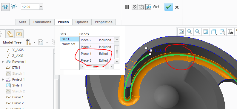
I was able to create a constant 12mm round now.
One more thing. I have excluded 2 pieces from the chain so the blend is smooth:
- Mark as New
- Bookmark
- Subscribe
- Mute
- Subscribe to RSS Feed
- Permalink
- Notify Moderator
- Mark as New
- Bookmark
- Subscribe
- Mute
- Subscribe to RSS Feed
- Permalink
- Notify Moderator
Hi MRV
When I try that on my PC (Creo 3.0 M090) it fails at 12 mm, 10 mm is OK.
- Mark as New
- Bookmark
- Subscribe
- Mute
- Subscribe to RSS Feed
- Permalink
- Notify Moderator
I have reordered the rounds.
First the 12mm round and then the 5 mm rounds.
I have used 12mm all over and 5mm only at one end.
- Mark as New
- Bookmark
- Subscribe
- Mute
- Subscribe to RSS Feed
- Permalink
- Notify Moderator
Hi MRV
I can see it now but, how did you select the chain in the references? When I try this I only get an edge.
- Mark as New
- Bookmark
- Subscribe
- Mute
- Subscribe to RSS Feed
- Permalink
- Notify Moderator
Select one edge then hold shift and select the remaining tangent edge.
or for non tangent edges, hold CTRL and select all the edges.
- Mark as New
- Bookmark
- Subscribe
- Mute
- Subscribe to RSS Feed
- Permalink
- Notify Moderator
I can create a chain but have you done this in a particular order? I have tried to copy your selection but my results are different!
- Mark as New
- Bookmark
- Subscribe
- Mute
- Subscribe to RSS Feed
- Permalink
- Notify Moderator
I usually select edges in an order.
For a chain you need to select the tangent edges in an order.
- Mark as New
- Bookmark
- Subscribe
- Mute
- Subscribe to RSS Feed
- Permalink
- Notify Moderator
Also in this case since you have used surfaces, the edges are not tangent all over. you need to select the missing edges along with the chains.
- Mark as New
- Bookmark
- Subscribe
- Mute
- Subscribe to RSS Feed
- Permalink
- Notify Moderator
I was able to create a constant 12mm round now.
One more thing. I have excluded 2 pieces from the chain so the blend is smooth:

- Mark as New
- Bookmark
- Subscribe
- Mute
- Subscribe to RSS Feed
- Permalink
- Notify Moderator
Hi MRV
I have tried to copy what you have done without success! No matter what I try I cannot get the same result. Are you using a later release of Creo 3.0 ? we have M090 here.
- Mark as New
- Bookmark
- Subscribe
- Mute
- Subscribe to RSS Feed
- Permalink
- Notify Moderator
Iam using Creo 3.0 M110.
- Mark as New
- Bookmark
- Subscribe
- Mute
- Subscribe to RSS Feed
- Permalink
- Notify Moderator
Hi MRV
I have finally solved it! ![]()
Looking at your picture and removing the two sections and it has worked.
Many Thanks for your help.
- Mark as New
- Bookmark
- Subscribe
- Mute
- Subscribe to RSS Feed
- Permalink
- Notify Moderator
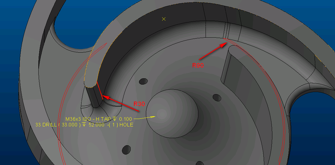
You have to switch the order of the 5er and ther 12er, yes, but that didn't cut it.
I had to add the highlighted rounds in order the get a working continous surface-surface round 12 (three sets needed).
No errors in the geometry check. ![]()
- Mark as New
- Bookmark
- Subscribe
- Mute
- Subscribe to RSS Feed
- Permalink
- Notify Moderator
Your problem arose from non tangency conditions in your sketches. Primarily SKETCH 1. Then by projecting you just transfer this non tangency along through all the features. You should have used splines to create the veins or converted all the segments to a single curve this would have helped. I reworked your file. It is attached.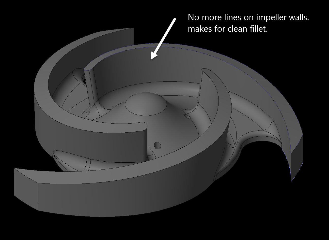
- Mark as New
- Bookmark
- Subscribe
- Mute
- Subscribe to RSS Feed
- Permalink
- Notify Moderator
Hi Ron
Thanks for that, how did you convert the segments to a single curve?
- Mark as New
- Bookmark
- Subscribe
- Mute
- Subscribe to RSS Feed
- Permalink
- Notify Moderator
There are two ways
1st this is what I did. I went in and redefined your sketch, I selected everything you had sketched, except for the small round on the inside tip of the vein. I then right mouse button and turned all your arcs into construction features. Then from the node of the small round left over I started drawing a spline. It was snapping to your construction curves, I put maybe 3-5 points along the length of the spline. When finished I chose the constraint for tangent and then forced the spline to be tangent tot he curve at the tip of the vein. Then I went and removed all the constraints on the points of the spline releasing them from your construction geometry. I did the same thing to the other side of the vein and finally I put an arc for the outer most diameter from the center to the end points of the 2 splines. I did this for both your projected Sketch 1 and then for the lower flat sketch.
Alternately you could just covert your geometry directly into splines by edit definition of your curve then select with cntrl all the lines you want to make into one spline. Then click the operations menu and convert to tab then spine on the drop down. I did not use this on your because you had some of your curves that were not tangent which would still make for a poor surface quality when making your round. 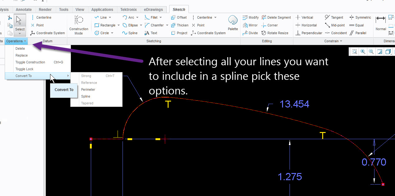
- Mark as New
- Bookmark
- Subscribe
- Mute
- Subscribe to RSS Feed
- Permalink
- Notify Moderator
Hi Ron
Just tried this method on a new impeller I'm working on with the same issue and it worked! ![]()
Wow, again I learn a new method.
Thanks for your input, very much appreciated!


