Community Tip - Want the oppurtunity to discuss enhancements to PTC products? Join a working group! X
- Community
- Creo+ and Creo Parametric
- 3D Part & Assembly Design
- Re: Varying Perimeter
- Subscribe to RSS Feed
- Mark Topic as New
- Mark Topic as Read
- Float this Topic for Current User
- Bookmark
- Subscribe
- Mute
- Printer Friendly Page
Varying Perimeter
- Mark as New
- Bookmark
- Subscribe
- Mute
- Subscribe to RSS Feed
- Permalink
- Notify Moderator
Varying Perimeter
Hello All,
I am hoping someone on this forum will be able to provide me with some guidence. I am trying to make a track assembly that is fully parameterized and can change to any size, by just editing a few parameters, like size, wheel spacing, etc. Currently, the point in the design process I am at is to build the track of the track assembly using a skeleton. The sketch I have follows the path of the wheels in a realistic manner, and changes accordingly, when I switch up the parameters. So far so good.
However, the issue I am having is for the next step in my design process, which is to add datums to my sketch, so that I can assemble my track links realistically. I am trying to access the varying perimeter from my sketch, but when I create a perimeter, it does not allow me to change the spacing and other attributes which I intended it to do. Does anyone know how to get that varying perimeter value which changes when I alter other dimensions? Or better yet, does anyone have a better idea for my design process?
I hope this post doesn't sound too ambiguous for anyone to understand. This is my first post here reaching out for help.
This thread is inactive and closed by the PTC Community Management Team. If you would like to provide a reply and re-open this thread, please notify the moderator and reference the thread. You may also use "Start a topic" button to ask a new question. Please be sure to include what version of the PTC product you are using so another community member knowledgeable about your version may be able to assist.
- Labels:
-
Data Exchange
- Mark as New
- Bookmark
- Subscribe
- Mute
- Subscribe to RSS Feed
- Permalink
- Notify Moderator
Hello Ethan and welcome to the forum.
I am having trouble picturing your question but the subject sounds familiar. What is not clear is the trouble you are having. Can you provide a few screenshots to clarify where the problem comes into play?
- Mark as New
- Bookmark
- Subscribe
- Mute
- Subscribe to RSS Feed
- Permalink
- Notify Moderator
Hi Antonius,
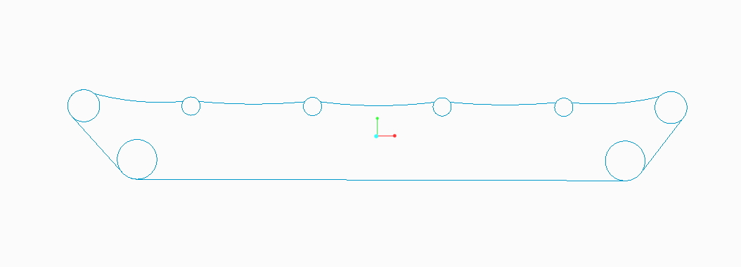
I am trying to make a sketch of a track assembly that is able to change dimensions. So for a skeleton model, I have this

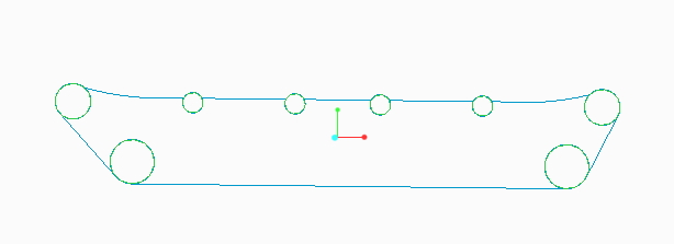
And I have referenced the outer sketch to the placement of the wheels so when I alter dimensions I can get a sketch like this

The sketch is only able to make subtle changes, but the perimeter changes for each regeneration. When I add a perimeter dimension to the outer track sketch, I get a regeneration error.
I want to know the perimeter value of any interation of the skech so I can properly space datums along the outer track in order to place my track links properly for each varied size.
- Mark as New
- Bookmark
- Subscribe
- Mute
- Subscribe to RSS Feed
- Permalink
- Notify Moderator
That makes more sense. The regeneration error is likely due to the fact that the sketch is not compatible with the changes. I find that the solver used for sketches doesn't like big jumps. In some cases, it might try to reverse a feature and the sketch becomes incompatible. Regardless, a robust sketch is a must for this type of problem.
You might try making the changes in smaller increments... or you might check the sketch for robustness by dragging features around and see how well they behave.
You might look into the measure tool to get the perimeter value.
- Mark as New
- Bookmark
- Subscribe
- Mute
- Subscribe to RSS Feed
- Permalink
- Notify Moderator
I am aware that the track assembly is not as robust...however regardless what my biggest issues is here is that I can not get the value of the perimeter a some sort of "variable" that I can then use for my next step of the design process. Is there any way I can store the varying value of the perimeter as some sort of variable to be used in relations?
- Mark as New
- Bookmark
- Subscribe
- Mute
- Subscribe to RSS Feed
- Permalink
- Notify Moderator
You can make the perimeter dimension driven by relations, sure.
- Mark as New
- Bookmark
- Subscribe
- Mute
- Subscribe to RSS Feed
- Permalink
- Notify Moderator
Here is an example of several ways to use a perimeter. The 1st is creating a perimeter dimension within the sketch, making the "slack" radius the variable. Test the sketch for robustness. The 1st time I created the perimeter dimension, I started at the lower horizontal line and it wouldn't change consistently; next I used the rear line of the track as a start. Now it behaved. I could not enter a value from limit to the other or it just failed but I can sneak up on it, or drag it. Both work fine.
The second example is the measure feature. It is placed in relations as a variable from the measurement feature parameter. Of course, they are the same... but one is a driving dimension (in the sketch) and one is the driven dimension (in the measurement feature). I suspect you want to make sure the track is a specific increment. You can do this with if statements in relations driving the driven perimeter dimension in the sketch.
If you want to do this through several levels, you can make the perimeter in the sketch a flexible dimension. It starts to get more complex from here, obviously, but it can be done.
Let us know what else needs clarification to get you to where you need to go.
- Mark as New
- Bookmark
- Subscribe
- Mute
- Subscribe to RSS Feed
- Permalink
- Notify Moderator
Oh, the little note on the model screen is a note with the relation from the measure feature.
If you are using Creo 2.0 full version, I can post the file (not academic compatible).
- Mark as New
- Bookmark
- Subscribe
- Mute
- Subscribe to RSS Feed
- Permalink
- Notify Moderator
Wow thank you for going into such detail. I am going to have to look at your strategy/approach more carefully and hopefully I'll be able to figure it out. I am using the Creo 2.0 full version, so if you can, I would love to see the file you have.
Thanks again
- Mark as New
- Bookmark
- Subscribe
- Mute
- Subscribe to RSS Feed
- Permalink
- Notify Moderator


