
Turn on suggestions
Auto-suggest helps you quickly narrow down your search results by suggesting possible matches as you type.
Showing results for
Please log in to access translation
Turn on suggestions
Auto-suggest helps you quickly narrow down your search results by suggesting possible matches as you type.
Showing results for
Community Tip - Have a PTC product question you need answered fast? Chances are someone has asked it before. Learn about the community search. X
- Community
- Creo+ and Creo Parametric
- 3D Part & Assembly Design
- Re: [WF3]Problem with bending sheet metal
Translate the entire conversation x
Please log in to access translation
Options
- Subscribe to RSS Feed
- Mark Topic as New
- Mark Topic as Read
- Float this Topic for Current User
- Bookmark
- Subscribe
- Mute
- Printer Friendly Page
[WF3]Problem with bending sheet metal
Jan 23, 2018
05:00 PM
- Mark as New
- Bookmark
- Subscribe
- Mute
- Subscribe to RSS Feed
- Permalink
- Notify Moderator
Please log in to access translation
Jan 23, 2018
05:00 PM
[WF3]Problem with bending sheet metal
Hi,
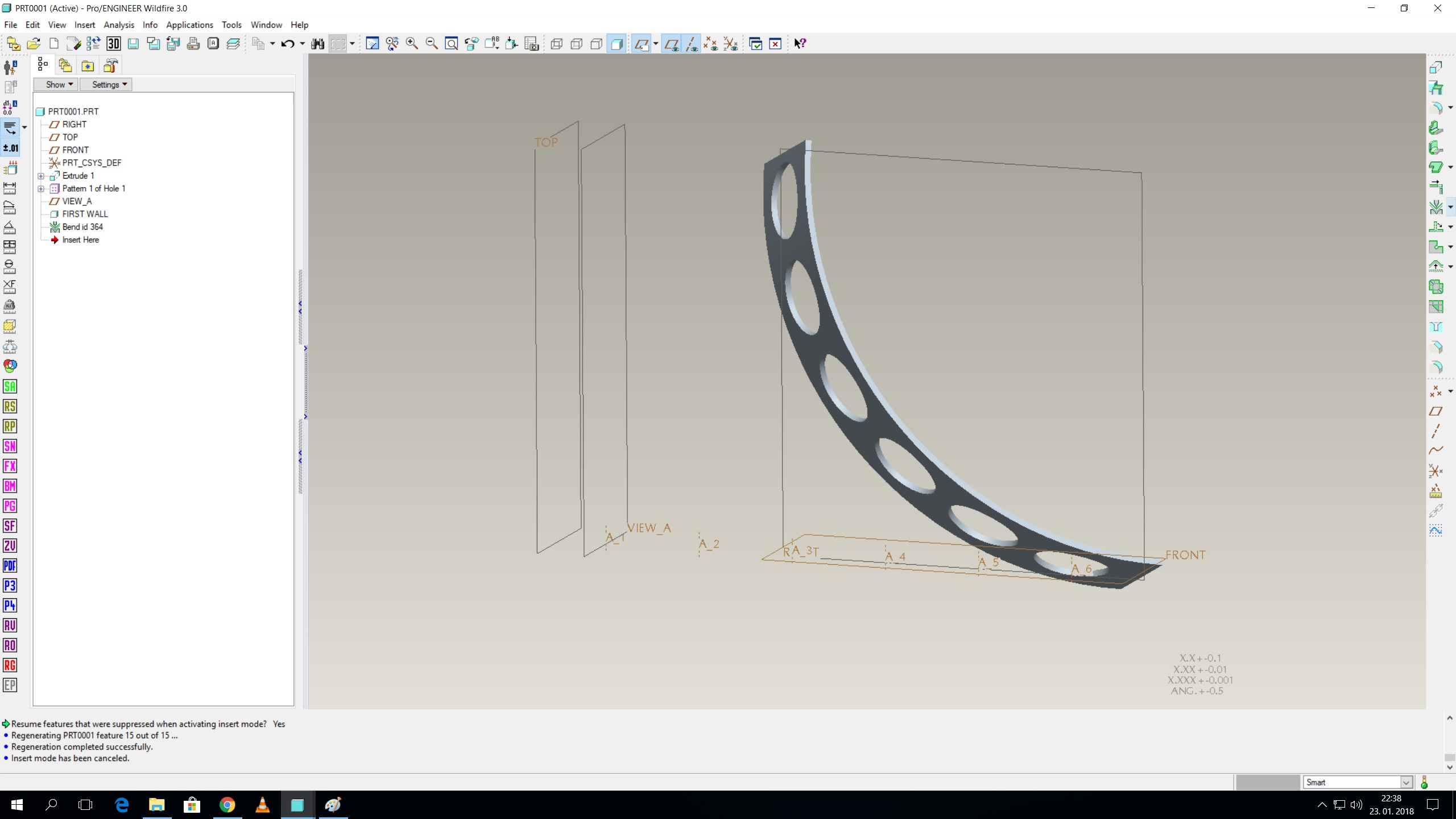
i have designed a plate that has a couple of holes in it. The plate will be first laser cut and then bent to a specific radius before installation. the plate basically acts as a spacer.
the problem is that i have to work with an older version of proe (wf3) and there are problems when bending the plate - centerlines of the holes stay where they were from the start, they do not bend with the model (see pic).
Thus i am not able to create a functional drawing, because i also have to also dimension the approx. angles between the holes. I would also like to have centerlines shown properly, because the drawing itself is more readable (the part is quite big and thin).
I need to have a plane across the first hole (with bend center as an axis - View A in the pic) so that i can also create a cross section view for the drawing. That also doesn't work.
any idea how can i accomplish that? I would like to avoid modelling it in a newer CAD, because i have to include it in an asm and mate some other components to it (the holes), which would be difficult with a STEP.
Wildfire 3, release something above 200.
thanks for any feedback.
Labels:
- Labels:
-
2D Drawing
3 REPLIES 3
Jan 24, 2018
10:22 AM
- Mark as New
- Bookmark
- Subscribe
- Mute
- Subscribe to RSS Feed
- Permalink
- Notify Moderator
Please log in to access translation
Jan 24, 2018
10:22 AM
Hi there,
I would create a reference point on the centre hole on the inner side, and a point on the outer side, then you can create an axis between those 2. ( repeat the sequence, for each hole )
The points and the axis can be used as a reference in the drawing to get the dimensions you need.
D.
Jan 25, 2018
07:17 AM
- Mark as New
- Bookmark
- Subscribe
- Mute
- Subscribe to RSS Feed
- Permalink
- Notify Moderator
Please log in to access translation
Jan 25, 2018
07:17 AM
Usually when I make a drawing of a part that was machined in the flat state and subsequently bent, the flat pattern dimensions are enough to define it properly. However, on those occasions where I need angular dimensions in the bent part, I resort to the following (for the part after the bend):
(1) Make an axis at the center of the part.
(2) Make angular offset planes through the center axis, one for each hole that needs a dimension.
(3) Use relations to define the angles. For most cases, I already know the angles of the holes, and used them to calculate the linear positions in the flat pattern. Thus, this is generally a simple "anglePlane = angleHole" equation.
(4) Now, you have nicely positioned planes that you can use for dimensions in the drawing.
If you need axes at the bent hole positions, you could take the further steps of creating them as intersections of the planes above and a plane through the holes that is perpendicular to the axis of the bend, but you don't need axes to create dimensions.
As for a plane for a cross section, just make that through the axis of the hole(s) prior to the bend feature.
A caveat, I can't even remember how far back we were using WF3, but I think all these things should work.
Jan 25, 2018
08:53 AM
- Mark as New
- Bookmark
- Subscribe
- Mute
- Subscribe to RSS Feed
- Permalink
- Notify Moderator
Please log in to access translation
Jan 25, 2018
08:53 AM
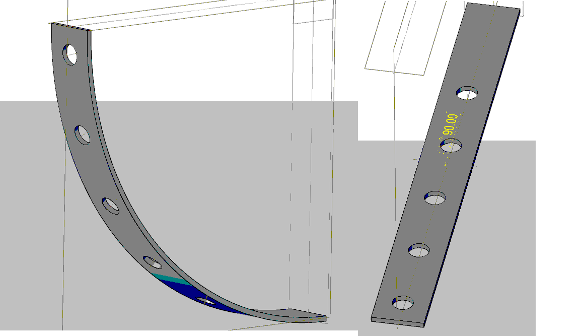
Hi, I would be tempted to model the component as you need it in the final installed condition rather than you attempting to fabricate from the flat. I did a quick model and extruded a plate that looks very similar I added an axis on the cl of the plate and did a radial hole that I then was able to pattern. When I flat pattern the part the axis is on the holes and it is also there in the design state.


