
Turn on suggestions
Auto-suggest helps you quickly narrow down your search results by suggesting possible matches as you type.
Showing results for
Please log in to access translation
Turn on suggestions
Auto-suggest helps you quickly narrow down your search results by suggesting possible matches as you type.
Showing results for
- Community
- Creo+ and Creo Parametric
- 3D Part & Assembly Design
- Re: When we place a ref balloon the size and refer...
Translate the entire conversation x
Please log in to access translation
Options
- Subscribe to RSS Feed
- Mark Topic as New
- Mark Topic as Read
- Float this Topic for Current User
- Bookmark
- Subscribe
- Mute
- Printer Friendly Page
When we place a ref balloon the size and references aren't the same as a normal balloon. Does anyone know a way to get both balloons in same size?
Dec 26, 2016
02:03 AM
- Mark as New
- Bookmark
- Subscribe
- Mute
- Subscribe to RSS Feed
- Permalink
- Notify Moderator
Please log in to access translation
Dec 26, 2016
02:03 AM
When we place a ref balloon the size and references aren't the same as a normal balloon. Does anyone know a way to get both balloons in same size?
When we place a ref balloon the size of reference balloons aren't the same as a normal balloon. Does anyone know a way to get both balloons in similar appearance?
Thanks in Advance.
This thread is inactive and closed by the PTC Community Management Team. If you would like to provide a reply and re-open this thread, please notify the moderator and reference the thread. You may also use "Start a topic" button to ask a new question. Please be sure to include what version of the PTC product you are using so another community member knowledgeable about your version may be able to assist.
Labels:
- Labels:
-
2D Drawing
23 REPLIES 23
Dec 26, 2016
03:02 AM
- Mark as New
- Bookmark
- Subscribe
- Mute
- Subscribe to RSS Feed
- Permalink
- Notify Moderator
Please log in to access translation
Dec 26, 2016
03:02 AM
You can set the min and max size of the balloon.
max_balloon_radius 0.000000
min_balloon_radius 0.000000
If the values are the same, you will have a consistent balloon.
Just make sure the value fits your intended annotation 
Dec 26, 2016
04:13 AM
- Mark as New
- Bookmark
- Subscribe
- Mute
- Subscribe to RSS Feed
- Permalink
- Notify Moderator
Please log in to access translation
Dec 26, 2016
04:13 AM
Thank you, Antonius Dirriwachter!
Dec 26, 2016
04:21 AM
- Mark as New
- Bookmark
- Subscribe
- Mute
- Subscribe to RSS Feed
- Permalink
- Notify Moderator
Please log in to access translation
Dec 26, 2016
04:21 AM
I just made maximum and minimum balloon radii are same, Even though I am getting same.
Dec 27, 2016
12:39 PM
- Mark as New
- Bookmark
- Subscribe
- Mute
- Subscribe to RSS Feed
- Permalink
- Notify Moderator
Please log in to access translation
Dec 27, 2016
12:39 PM
I just tested this with a large balloon.
I set the min and max 1.5" and this is working.
Can you post the file with the problem?
Dec 28, 2016
09:24 AM
- Mark as New
- Bookmark
- Subscribe
- Mute
- Subscribe to RSS Feed
- Permalink
- Notify Moderator
Please log in to access translation
Dec 28, 2016
09:24 AM
I've tried that with no success as well. It was also on repeat regions if I remember correctly.
Dec 27, 2016
12:53 PM
- Mark as New
- Bookmark
- Subscribe
- Mute
- Subscribe to RSS Feed
- Permalink
- Notify Moderator
Please log in to access translation
Dec 27, 2016
12:53 PM
I expected Antonius answer to work then I re-read the original post, Is this a balloon from a repeat region and the reference balloon? If it is, these are symbols, possibly custom symbols that would need to be corrected.
As Antonius asks, more information would probably get you a better answer.
Dec 28, 2016
02:53 AM
- Mark as New
- Bookmark
- Subscribe
- Mute
- Subscribe to RSS Feed
- Permalink
- Notify Moderator
Please log in to access translation
Dec 28, 2016
02:53 AM
Hi Antonius and Stephen, Thank you for your replies!
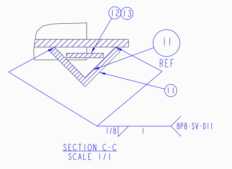
In this below view, we can see the size difference between the reference balloon and the normal balloon. This is the main problem facing when I want to place the reference balloon in another view.
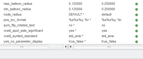
- maximum and minimum radii values of balloons
Dec 28, 2016
10:09 AM
- Mark as New
- Bookmark
- Subscribe
- Mute
- Subscribe to RSS Feed
- Permalink
- Notify Moderator
Please log in to access translation
Dec 28, 2016
10:09 AM
There are 2 "balloons" in Creo.
The "balloons" the config option max/min balloon radius controls are note balloons created under annotations. This option will NOT affect repeat region BOM balloons.
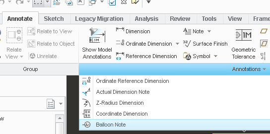
I believe you are referring to BOM balloons that are generated from the TABLE tab under create balloons. These are control by symbols located in the folder "LOADPOINT"\Common Files\MXXX\symbols\report\bomballoon\ .

To correct the size, you will have to edit the symbols.
Dec 28, 2016
10:28 AM
- Mark as New
- Bookmark
- Subscribe
- Mute
- Subscribe to RSS Feed
- Permalink
- Notify Moderator
Please log in to access translation
Dec 28, 2016
10:28 AM
Yup. I had at one time toyed with the idea of using the functionality of using a "custom" symbol that the repeat region allows, but never had time to try it. It IS frustrating having 2 different size balloons!
Dec 28, 2016
10:37 AM
- Mark as New
- Bookmark
- Subscribe
- Mute
- Subscribe to RSS Feed
- Permalink
- Notify Moderator
Please log in to access translation
Dec 28, 2016
10:37 AM
It can be fixed BUT once you add the reference balloon to a drawing you will probably not be able to fix that drawing. For whatever reason, that reference balloon is locked in at that point. Maybe PTC can fix it in the code or maybe they know the trick to fixing it, I have never found a way once the reference balloon is added.
I don't specifically remember about the default symbols but what I have done in the past is adjust the text height on the balloons to make them appear close to the same size instead of messing with the symbol definitions. If I remember correctly, the balloon diameter is adjust by the text height (but so is the text so it's not always a good solution).
Dec 28, 2016
11:53 AM
- Mark as New
- Bookmark
- Subscribe
- Mute
- Subscribe to RSS Feed
- Permalink
- Notify Moderator
Please log in to access translation
Dec 28, 2016
11:53 AM
Not just text height, but also whether there are 1 or 2 or 3 characters in the balloon. Gah!
Instead of min and max balloon size, we need a single size for ALL balloon notes, and it's up to us to make sure it's the right size.
Dec 28, 2016
01:44 PM
- Mark as New
- Bookmark
- Subscribe
- Mute
- Subscribe to RSS Feed
- Permalink
- Notify Moderator
Please log in to access translation
Dec 28, 2016
01:44 PM
Obviously, repeat regions don't excite me either.
PTC could easily fix this by adding a "fixed_balloon_size" option with zero would be dynamic as it is today, or you can give it a value where ALL balloons would be constant.
A constant balloon size is as common as a constant text height in many organizations.
Yes, symbols can size to text height in the symbol library. Just created my 4th useful symbol yesterday.
Dec 28, 2016
02:54 PM
- Mark as New
- Bookmark
- Subscribe
- Mute
- Subscribe to RSS Feed
- Permalink
- Notify Moderator
Please log in to access translation
Dec 28, 2016
02:54 PM
BOM balloons are awesome with about a million caveats. I have worked at places that require driven BOMs and have a ton of controls in place to enforce and support them. Currently, the place I am at now, only a few use them. They work great in certain instances and makes life easy for those. I currently have a drawing that someone mixed balloon notes and repeat region balloons...NOT a good mix and leads to way too many inconsistencies.
Dec 28, 2016
03:09 PM
- Mark as New
- Bookmark
- Subscribe
- Mute
- Subscribe to RSS Feed
- Permalink
- Notify Moderator
Please log in to access translation
Dec 28, 2016
03:09 PM
true.
I've worked where the entire CAD drawing library was sent to contract services in India to incorporate ECOs.
What came back was unsustainable when they tried to bring it back in-house.
It took less than 3 months to create a $1M hole in what was otherwise a pretty solid CAD environment (NX).
If I have 50 part BOMs, it is rare. I also need to create references and manage the quantities on a group basis.
And I have a habit of grouping my component types within a BOM.
In the end, it is faster to just to fill in a table. I know how to check my work. I also know that nothing will change out of the blue.
I certainly am not defending my lack of use of capabilities that we pay good money for.
But as Stephen so rightly suggests, this type of environment requires diligence, enforcement, and sometimes extra resources.
Take your eyes of that, and all goes out the window very quickly.
Dec 28, 2016
05:21 PM
- Mark as New
- Bookmark
- Subscribe
- Mute
- Subscribe to RSS Feed
- Permalink
- Notify Moderator
Please log in to access translation
Dec 28, 2016
05:21 PM
Lesson learned: don;t send anything important to India...... 
We're running into that on the project I'm on....ugh.....
I used to absolutely hate repeat regions as well. Then, since the companies I worked for insisted on using them, I dug in and became pretty proficient in them, aided by looking at tables very experienced users had set up. I think I learned a lot from looking at their work, and now I actually insist on using them in anything I do, and set them up for companies I've worked for. Yes, there are some things that make you want to tear your hair out (like flexible parts suddenly switching their index # at random...) and other quirks, but there are some really neat trick you can do. I set mine up so that any parts made with certain start parts (for bulk stuff like oil, paint, Loc-Tite, etc., to automatically come in with a Qty of "A/R", or be able to switch that as needed by index to be anything you want (i.e. 1 gallon). I also made "REMOVED" parts that would automatically blank the entire row of a BOM. I was able to automatically sort the tables to have made (in-house) assemblies come in at the bottom, then above that purchased (non-modified) assemblies, then made parts, then sourced (non-modified) parts, then all the weld filler, fasteners, and then bulk parts etc. The employer like a sorted BOM, so I made one. It was fun, and I learned a lot, so, I guess I've switched sides now.
But yes, they CAN be a major PITA, especially with respect to the flexible part (spring) issue switching indexes even if the index was fixed manually. I found a way to FORCE it to stay fixed, but man, what a PITA, and a potentially a major problem. Not sure yet if they've fixed that....
Dec 28, 2016
05:53 PM
- Mark as New
- Bookmark
- Subscribe
- Mute
- Subscribe to RSS Feed
- Permalink
- Notify Moderator
Please log in to access translation
Dec 28, 2016
05:53 PM
We may have strayed a bit from the main topic
The only other problem with systems like that, although there are work-arounds, is the "model doesn't match the BOM" issues.
Invariably, I had separable part files... meaning I had a, let's say, a switch with the nut and washer as separate items so you can see sections properly. So the solution, before flexible parts in assembly, was to model each part and create the switch assembly within the larger assembly. Now you have 3 parts dedicated to a switch in the using assembly. The only thing the system would understand is putting the switch together in a sub-assembly at the right distance. Meaning, you would have several versions of the same switch floating around on the system. The flexible assembly solves that, but as you rightly noted, it was again poorly implemented, although to the Specification, of course.
In my world, the tool cannot dictate results. If I have to spend 10 hours to save 30 minutes, it is on me. There are so precious few elements that I can automate that usually, the effort has no return. If I cannot reliably put 10 items on a manual BOM at any point in my design cycle, I am in the wrong business.
Dec 28, 2016
08:23 PM
- Mark as New
- Bookmark
- Subscribe
- Mute
- Subscribe to RSS Feed
- Permalink
- Notify Moderator
Please log in to access translation
Dec 28, 2016
08:23 PM
Yeah, I hear ya! It should be noted that there is a world of difference between the user working for himself for customers, and a user who works directly for a big corporation. Flexibility vs. inflexibility. BUT, if I can spend 10 hours on something that saves every user in the company 30 min each time they use it, then in that case it's well worth it. For the contractor, it's diminishing returns. For the corporate world, it's time-saving automation.
I think in my case, I've gotten to learn a lot about the repeat regions I wouldn't normally have been able to.....and it makes me look good to da boss man.
Now, if only they'd fix the bugs.....
Dec 28, 2016
09:11 PM
- Mark as New
- Bookmark
- Subscribe
- Mute
- Subscribe to RSS Feed
- Permalink
- Notify Moderator
Please log in to access translation
Dec 28, 2016
09:11 PM
The bugs came from the poor specification for features built on the core.
It is starting to look like these "specifications" were written specifically to make sure the core isn't touched.
Dec 28, 2016
07:38 PM
- Mark as New
- Bookmark
- Subscribe
- Mute
- Subscribe to RSS Feed
- Permalink
- Notify Moderator
Please log in to access translation
Dec 28, 2016
07:38 PM
I found setting each component to have a feature parameter for the index made all the index fixing problems go away. Plus one can create a 'removed part' and assemble it once for each removed item, by giving each the appropriate index number. Any 'reference' parts can be excluded by giving them a special value for the index feature parameter or just remove the parameter and exclude them by filter.
These values are repeat region invariant; they are part of the model description, so they can be used with simplified reps. If one wants to ensure each item can't be called out in more than one view, adding a separate component parameter can be used to sub-group. E.g. if the parameter is view_name, then a table can filter on view_name. Only those items matching the view_name can be shown on the table and cannot be shown anywhere else. If the parameter value for view_name is changed, the item is removed from the initial table and is added to the new one, so there is no way to have duplicate balloons/incorrect quantities.
A lot of this effort could be skipped if Creo didn't leave separation between assemblies and the simplified reps of those assemblies. I expect there is an underlying structural reason that PTC decided they didn't want to bridge. Mainly the problem lies with Repeat Regions being a secondary data extraction that ends up unrelated to the model; one can create multiple repeat regions for a single model and each can have a different index and filter and repeat region relations.
The best part is that component parameter assignments can take place in advance of making drawings, allowing external systems to be primed with the index values. Not a problem for small shops, but for those with large assemblies or large numbers of assemblies that depend on ERP systems, it seems like a great way to provide an extractable cross-check.
It is important that the ERP system isn't compromised with its own fake entries - like using labels or comment fields instead of links to assembly and part records, which can ruin item count comparisons.
Finally - REF balloons are painful to use and manage. Repeat regions have been a tacked-on function that demos great for like 5 items, as long as those items don't have alternates, aren't going to be grouped into a family table, etc. Most of my work used symbols and off-drawing PLs so there was no effort at all required to make the balloons the same - they were already the same.
Dec 28, 2016
08:25 PM
- Mark as New
- Bookmark
- Subscribe
- Mute
- Subscribe to RSS Feed
- Permalink
- Notify Moderator
Please log in to access translation
Dec 28, 2016
08:25 PM
"I found setting each component to have a feature parameter for the index made all the index fixing problems go away."
How would that work then for parts used in a bunch of different assemblies?
Dec 29, 2016
12:15 AM
- Mark as New
- Bookmark
- Subscribe
- Mute
- Subscribe to RSS Feed
- Permalink
- Notify Moderator
Please log in to access translation
Dec 29, 2016
12:15 AM
The parameter is for the component as a feature in the assembly - it is only applicable to the assembly. It is not a part/assembly parameter. I recall they are referred to as cparam rather than param.
Dec 29, 2016
09:37 AM
- Mark as New
- Bookmark
- Subscribe
- Mute
- Subscribe to RSS Feed
- Permalink
- Notify Moderator
Please log in to access translation
Dec 29, 2016
09:37 AM
Since I like to use flexible parts, I'll look into that, thanks!
Dec 28, 2016
08:34 PM
- Mark as New
- Bookmark
- Subscribe
- Mute
- Subscribe to RSS Feed
- Permalink
- Notify Moderator
Please log in to access translation
Dec 28, 2016
08:34 PM
We ended up fooling Teamcenter (UG-NX PDM) by only accepting properly formatted file names (according to part number) for the BOM extraction into another purchasing system that maintained the true BOMs. That way, the 3 switch part numbers could be xxxxx-1 xxxxx-2 and xxxxx-3 while the models carried an empty xxxxx.prt which is recognized by the routine.
I also have clients that maintain separate BOMs for purchasing. In the long run, it was better for me to manage BOMs on the drawing and making the purchase system secondary to the drawings.
Nothing worse than not having to share data that is incomplete.
After all these years, I have been able to avoid relations that tie drawings and models together. I did do that at one time by filling in title block and such. Not worth the maintenance in my working environment.


