
Turn on suggestions
Auto-suggest helps you quickly narrow down your search results by suggesting possible matches as you type.
Showing results for
Please log in to access translation
Turn on suggestions
Auto-suggest helps you quickly narrow down your search results by suggesting possible matches as you type.
Showing results for
Community Tip - New to the community? Learn how to post a question and get help from PTC and industry experts! X
- Community
- Creo+ and Creo Parametric
- 3D Part & Assembly Design
- X,Y formated annotations in drawings
Translate the entire conversation x
Please log in to access translation
Options
- Subscribe to RSS Feed
- Mark Topic as New
- Mark Topic as Read
- Float this Topic for Current User
- Bookmark
- Subscribe
- Mute
- Printer Friendly Page
X,Y formated annotations in drawings
Sep 25, 2013
01:18 PM
- Mark as New
- Bookmark
- Subscribe
- Mute
- Subscribe to RSS Feed
- Permalink
- Notify Moderator
Please log in to access translation
Sep 25, 2013
01:18 PM
X,Y formated annotations in drawings
Hi,
is it possible to apply (x, y) style for annotate formats in drawing file?
thanks
This thread is inactive and closed by the PTC Community Management Team. If you would like to provide a reply and re-open this thread, please notify the moderator and reference the thread. You may also use "Start a topic" button to ask a new question. Please be sure to include what version of the PTC product you are using so another community member knowledgeable about your version may be able to assist.
Labels:
- Labels:
-
2D Drawing
4 REPLIES 4
Sep 25, 2013
02:22 PM
- Mark as New
- Bookmark
- Subscribe
- Mute
- Subscribe to RSS Feed
- Permalink
- Notify Moderator
Please log in to access translation
Sep 25, 2013
02:22 PM
Yes you can... I'm sure of it - but you'll have to give us more information to say for sure and exactly how to accomplish this.
Sep 25, 2013
03:35 PM
- Mark as New
- Bookmark
- Subscribe
- Mute
- Subscribe to RSS Feed
- Permalink
- Notify Moderator
Please log in to access translation
Sep 25, 2013
03:35 PM
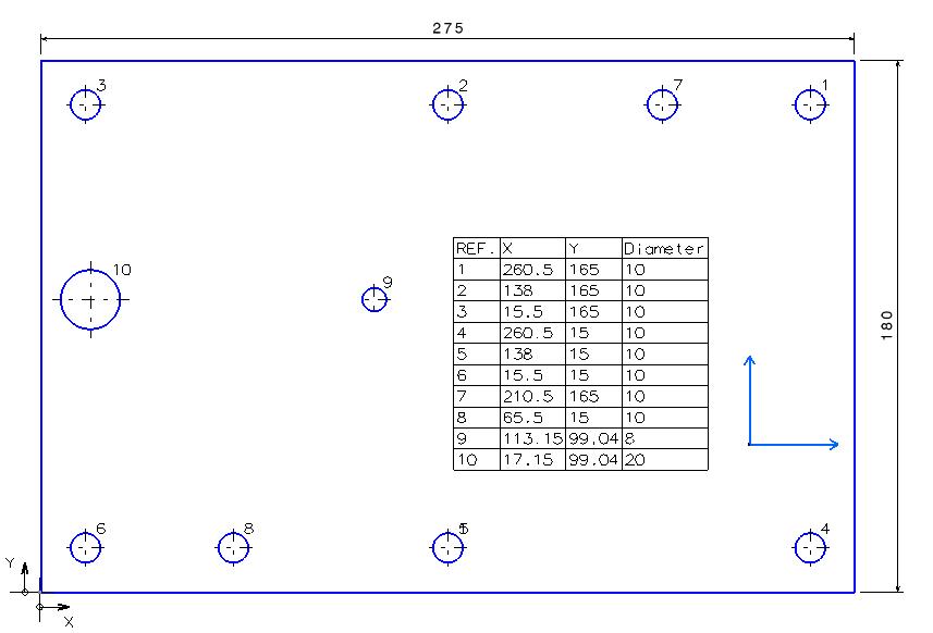
suppose you want to annotate coordinates of multiple holes on a plate according to a ref point. (x,y) format is very handy for performing manual machining or manual nc code programming. below pic is an example approch in catia:
Sep 25, 2013
04:47 PM
- Mark as New
- Bookmark
- Subscribe
- Mute
- Subscribe to RSS Feed
- Permalink
- Notify Moderator
Please log in to access translation
Sep 25, 2013
04:47 PM
Now that makes it a whole lot easier to discuss.
I can see doing this in a manual way by loading the table with dimensions and relations. They will remain associative. As long as the dimension style stays simple like this (no dual dims or special tolerance display) this is more than achievable.
I would like to know from people who do this on a regular basis to post with regard to this. I am certain I don't know the -easiest- way to accomplish this.
Please confirm what you have access to. Are you making the model, or just creating the drawings? Ideally, this is a native Pro/E-WF-Creo model and you have access or input to the modeling process.
Sep 26, 2013
08:23 AM
- Mark as New
- Bookmark
- Subscribe
- Mute
- Subscribe to RSS Feed
- Permalink
- Notify Moderator
Please log in to access translation
Sep 26, 2013
08:23 AM
If it is a native Pro/E or Creo part and the holes are created with the 'hole' tool then you can use the Hole Table facility in the drawing, you need a co-ordinate system with X and Y pointing in the right direction and then it will automatically number the holes and tell you the x, y and diameters of the holes.
They can be labelled in different ways and sorted in different ways. The only downside is that you may need to replace the table/update it when the pattern changes. It's been a while since I added one to a drawing and am not at my CAD station right now, from memory Tools > Hole Table then you can Setup and Create


