
Turn on suggestions
Auto-suggest helps you quickly narrow down your search results by suggesting possible matches as you type.
Showing results for
Please log in to access translation
Turn on suggestions
Auto-suggest helps you quickly narrow down your search results by suggesting possible matches as you type.
Showing results for
Community Tip - Want the oppurtunity to discuss enhancements to PTC products? Join a working group! X
- Community
- Creo+ and Creo Parametric
- 3D Part & Assembly Design
- Re: adding text to a name plate, then text is expl...
Translate the entire conversation x
Please log in to access translation
Options
- Subscribe to RSS Feed
- Mark Topic as New
- Mark Topic as Read
- Float this Topic for Current User
- Bookmark
- Subscribe
- Mute
- Printer Friendly Page
adding text to a name plate, then text is exploded upon export to .DWG?
Dec 02, 2013
03:53 PM
- Mark as New
- Bookmark
- Subscribe
- Mute
- Subscribe to RSS Feed
- Permalink
- Notify Moderator
Please log in to access translation
Dec 02, 2013
03:53 PM
adding text to a name plate, then text is exploded upon export to .DWG?
Why is it that text on a pro-e wildfire or creo modeled panel or name plate is exploded to lines when exported to a .dwg file from a 2D layout? What do you have to do to achieve getting editable text when it is exported to a .dwg file? Must you use annotate?
This thread is inactive and closed by the PTC Community Management Team. If you would like to provide a reply and re-open this thread, please notify the moderator and reference the thread. You may also use "Start a topic" button to ask a new question. Please be sure to include what version of the PTC product you are using so another community member knowledgeable about your version may be able to assist.
Labels:
- Labels:
-
2D Drawing
27 REPLIES 27
Dec 02, 2013
03:58 PM
- Mark as New
- Bookmark
- Subscribe
- Mute
- Subscribe to RSS Feed
- Permalink
- Notify Moderator
Please log in to access translation
Dec 02, 2013
03:58 PM
Geometry text is created from curves, not text as normal. It is a special interface that allows you to manipulate it as text but it is not recognized in any of the export formats that I know of.
Dec 02, 2013
04:26 PM
- Mark as New
- Bookmark
- Subscribe
- Mute
- Subscribe to RSS Feed
- Permalink
- Notify Moderator
Please log in to access translation
Dec 02, 2013
04:26 PM
I know that annotations used as notes are editable when exported. But you can't position them near as easily as text for exact location. Are using annotation notes the only way to get editable text after export to .dwg?
Dec 02, 2013
07:47 PM
- Mark as New
- Bookmark
- Subscribe
- Mute
- Subscribe to RSS Feed
- Permalink
- Notify Moderator
Please log in to access translation
Dec 02, 2013
07:47 PM
True, annotation exports are a good feature but not all the style settings for the text are exported. It is almost hit and miss if you need it to be placed properly.
Dec 03, 2013
09:20 AM
- Mark as New
- Bookmark
- Subscribe
- Mute
- Subscribe to RSS Feed
- Permalink
- Notify Moderator
Please log in to access translation
Dec 03, 2013
09:20 AM
So there is no way to export text without it being exploding into lines and there is no way to use mtext with the accuracy of text. It seems like some things we are never going to realize. Jet packs, world peace and something from PTC that gives you what you need without jumping through a dozen hoops just to find out that you are baclk where you started.
Dec 03, 2013
10:38 AM
- Mark as New
- Bookmark
- Subscribe
- Mute
- Subscribe to RSS Feed
- Permalink
- Notify Moderator
Please log in to access translation
Dec 03, 2013
10:38 AM
The text in features is converted into arcs and curves by Sketcher - long before being exported.
What you are looking for seems more in line with the capabilities of Adobe Illustrator, possibly Inkscape.
Dec 03, 2013
01:20 PM
- Mark as New
- Bookmark
- Subscribe
- Mute
- Subscribe to RSS Feed
- Permalink
- Notify Moderator
Please log in to access translation
Dec 03, 2013
01:20 PM
We have jet packs now 
Dec 03, 2013
02:51 PM
- Mark as New
- Bookmark
- Subscribe
- Mute
- Subscribe to RSS Feed
- Permalink
- Notify Moderator
Please log in to access translation
Dec 03, 2013
02:51 PM
I'm sorry but where would you like to export this text? To AutoCAD?
Dec 03, 2013
03:16 PM
- Mark as New
- Bookmark
- Subscribe
- Mute
- Subscribe to RSS Feed
- Permalink
- Notify Moderator
Please log in to access translation
Dec 03, 2013
03:16 PM
Yes. All our models are done in Pro-E (Creo now) and exported to Dwg to be manipulated and prepared for manufacturing. When changes are made to text in the field of the dwg, it has to be erased and replaces with acad text or mtext. We have a lot of face plates with switches and knobs (instrumentation panels) and nomenclature on the plate stating what each one is. It would be real nice if, after the dwg is spit out of Pro-e, it didn't have to be periodically replaced whenever the nomenclature changes. All our instrumentation panels are created in Pro-E and there may be a lot of text used in the model. It all comes out worthless lines in a dwg or dxf.
Dec 03, 2013
04:00 PM
- Mark as New
- Bookmark
- Subscribe
- Mute
- Subscribe to RSS Feed
- Permalink
- Notify Moderator
Please log in to access translation
Dec 03, 2013
04:00 PM
I know your pain. It's as much a problem that PTC doesn't support the DWG output as that manufacturing doesn't use the Pro/E models.
Since Illustrator is not budget friendly and Inkscape is open-source, these were not available to users; instead they who would gen up artwork for panels and such either in Pro/E, or in Visio or Canvas ot Word or Powerpoint. Then manufacturing or the supplier would usually create their own artwork anyway.
Dec 03, 2013
04:24 PM
- Mark as New
- Bookmark
- Subscribe
- Mute
- Subscribe to RSS Feed
- Permalink
- Notify Moderator
Please log in to access translation
Dec 03, 2013
04:24 PM
Ok,only annotation texts can be exported from 2D drawings resulting as TEXT or MTEXT entities in ACAD.
Modeled text, that can be made using sketches, will show up as curves and lines in the exported DWG.
What is the problem with annotation positioning?
Dec 04, 2013
04:51 PM
- Mark as New
- Bookmark
- Subscribe
- Mute
- Subscribe to RSS Feed
- Permalink
- Notify Moderator
Please log in to access translation
Dec 04, 2013
04:51 PM
Annotations are treated as notes and therefore do not have the positioning constraints that regular text does in Pro-E. The nomenclature I need to put down has to be of the exact font (RomanS), exact size and exact position.
Though you can acheive some of this with annotations, the positioning is a bear to deal with.
Dec 05, 2013
01:58 AM
- Mark as New
- Bookmark
- Subscribe
- Mute
- Subscribe to RSS Feed
- Permalink
- Notify Moderator
Please log in to access translation
Dec 05, 2013
01:58 AM
Hello,
I guess it would be best for you to deal with annotations positioning inside of the drawing. You can use some sketched entities, or draft grid for exact positioning. For the note to stay in fixed position you can just relate it to the view.
This certainly isn't like doing the same work in ACAD, but anyway I don't think positioning of text is easier to do in sketcher.
Dec 05, 2013
01:30 PM
- Mark as New
- Bookmark
- Subscribe
- Mute
- Subscribe to RSS Feed
- Permalink
- Notify Moderator
Please log in to access translation
Dec 05, 2013
01:30 PM
Actually, text in Pro-e is fairly easy to locat, adjust, alter & constrain in Sketcher or directly to the model. Not like autocad because it is single line text but .... if only ... why must it be converted to lines upon export ...#!!? PTC, really, after all this time...
Dec 05, 2013
01:54 PM
- Mark as New
- Bookmark
- Subscribe
- Mute
- Subscribe to RSS Feed
- Permalink
- Notify Moderator
Please log in to access translation
Dec 05, 2013
01:54 PM
Ok, so the problem with Pro/E annotation is that it maybe shifts slightly on export? Or rather on import to ACAD?
You can get editable TEXT or MTEXT entities if you use TTF font in Pro/E, so it doesn't get convereted to lines, just have to have the DWG export settings right.
Dec 05, 2013
02:11 PM
- Mark as New
- Bookmark
- Subscribe
- Mute
- Subscribe to RSS Feed
- Permalink
- Notify Moderator
Please log in to access translation
Dec 05, 2013
02:11 PM
That is the problem with all the DWG exports I've ever done is that certain aspects of a font are not translated and this causes many issues with overlapping and incorrect formatting. This has always been a problem and not just Creo/WF/Pro|E. Adding TTF to the mix just made it worse, not better because you are dependent on those external font "compatibility" files.
One really nice thing about all this text being curves is that your intent cannot be lost. You can always verify your intent with the output. And if it was me, if "manufacturing" changed something, I would want it back annotated back to my design level files anyway so that the intent document (design) is always correct. I know this might sound like an excuse for PTC, but if I had to make the design choice, I wouldn't do it any differently.
But having said that, yes, I do wish text was more universal in the translators by now... even "auto-generate font" is something that should be available by now within converters. We use to have innovation on the fly with regard to CAD, but today... we seem to be stagnant. Too many developers either chasing ghosts or inventing yet another UI for the same old box with a new wrapper. And I'm not talking PTC here, this is universal in the coding world. What has been the latest innovation, really? All I can think of smarter robots... and that's only because it is fun as school projects and winning games. Heck, even the old translators are getting a new name and calling it better. HA! Again, same box, new wrapper!
Dec 05, 2013
02:36 PM
- Mark as New
- Bookmark
- Subscribe
- Mute
- Subscribe to RSS Feed
- Permalink
- Notify Moderator
Please log in to access translation
Dec 05, 2013
02:36 PM
Well, I've got ACAD 2013 at my disposal at the moment. So, we could do some tests, I'd say any TTF font can be converted as long as you don't use special characters, or diacritic marks.
Positioning can be fixed in ACAD pretty easily. Just give me an example file.
You know things like %%c for diameter symbol in AutoCAD will always stay being AutoCAD only.
Dec 05, 2013
02:51 PM
- Mark as New
- Bookmark
- Subscribe
- Mute
- Subscribe to RSS Feed
- Permalink
- Notify Moderator
Please log in to access translation
Dec 05, 2013
02:51 PM
Text is certainly easy. It's the detailed appearance of text that is a difficult task to manage. Font kerning pairs and glyph hints, for example, are not likely to be universally dealt with because the results are subject to software interpretation. TTFs are little programs that are executed by a font interpreter. Then the locations of each letter are determined by another interpreter - the info for locating them isn't in the text file.
This is the reason I first suggested handling it in Illustrator. Adobe has a well developed font description chain from the keyboard to the printing press. If what text looks like and where text is located are important, then Illustrator is currently the best choice.
Dec 05, 2013
02:34 PM
- Mark as New
- Bookmark
- Subscribe
- Mute
- Subscribe to RSS Feed
- Permalink
- Notify Moderator
Please log in to access translation
Dec 05, 2013
02:34 PM
Pro/E doesn't convert sketched text for export because Sketcher already converted the sketched text to lines and arcs. Exporting has nothing to do with that conversion. Because Sketcher does this, you can create datum references and surface and solid geometry based on the Sketched text.
What is it that manufacturing does that depends on this? Dxf or dwg files don't contain the font definitions, so how would they match what's in Sketcher if all that was sent was the text?
Dec 05, 2013
05:14 PM
- Mark as New
- Bookmark
- Subscribe
- Mute
- Subscribe to RSS Feed
- Permalink
- Notify Moderator
Please log in to access translation
Dec 05, 2013
05:14 PM
Just to clear this up, manufacturing has nothing to do with it. Drafting may need to change the text size, nomenclature, or position of marking on, let's say, an instrument panel. Since Pro-E's 2D drafting completely sucks, especially for busy drawings, we have to export all our models to 2D AutoCAD where the information can be arranged, dimensioned and such. As can happen and often does, things change and because things change, a lot of now useless text has to be redrawn in AutoCAD. Reentered, sized, justified…. If a panel is good but there is another one like it but the nomenclature is different. Again, the dummied down Pro-E text has to be removed and new MText put in its place.
Dec 06, 2013
12:27 AM
- Mark as New
- Bookmark
- Subscribe
- Mute
- Subscribe to RSS Feed
- Permalink
- Notify Moderator
Please log in to access translation
Dec 06, 2013
12:27 AM
It's been a very long time since I've heard of anyone exporting a dxf/dwg for a purpose other than: A) manufacturing; B) insurance for the customer they can have something simple to work from in case civilization ends.
If you are stuck with using drafting for this it seems like there's a need for some JLink or Weblink work to extract the Pro/E text and locations and generate an Autodesk macro to reproduce it. Check with www.proetoolbox.co.uk for Weblink (and AutoIT) or http://inversionconsulting.blogspot.com/ (no connection with either.) There are others who can also provide help, like. http://www.felcosolutions.com/. There are likely to be thousands of places to get help on the AutoCAD side; extracting the data is the problem you are currently faced with, so it's a good place to start.
Dec 18, 2013
03:06 PM
- Mark as New
- Bookmark
- Subscribe
- Mute
- Subscribe to RSS Feed
- Permalink
- Notify Moderator
Please log in to access translation
Dec 18, 2013
03:06 PM
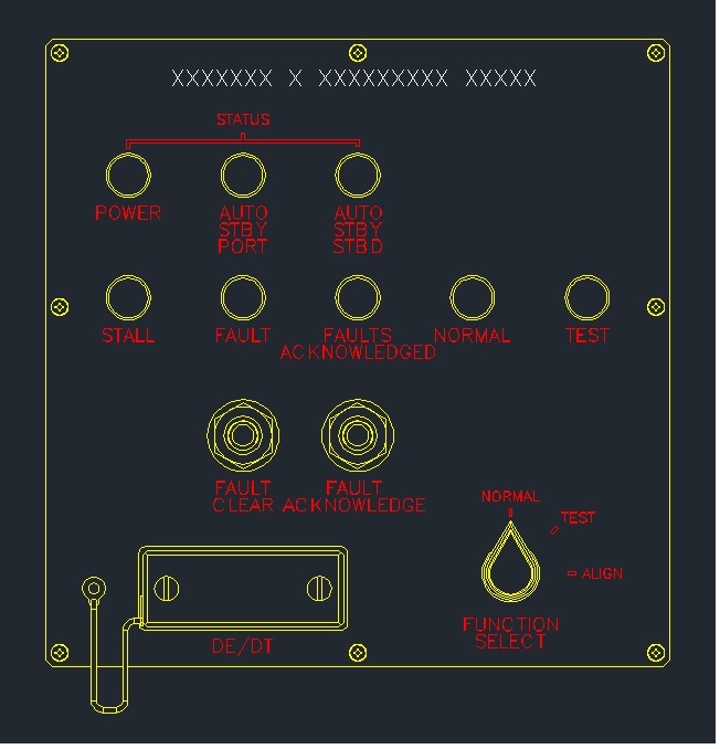
Just to give you an idea of what we are doing, here is an image of a single panel (for some jobs, there are many) that originated as a Crea Parametric 3D model. It gets "save copy" to dwg. Then, all line fonts must be replaced with functional text in Autocad.
Dec 18, 2013
03:25 PM
- Mark as New
- Bookmark
- Subscribe
- Mute
- Subscribe to RSS Feed
- Permalink
- Notify Moderator
Please log in to access translation
Dec 18, 2013
03:25 PM
I do a lot of silkscreen requirement drawings. Say I have a panel with silkscreen, then I specify every applicable dimension that allows re-creation of the silkscreen with an appropriate application. Since the fabrication shop is responsible to acquire the film and are responsible for accuracy, this is the best way for me to get exactly what I want. Very high resolution art, specific font sets, full control of line weights, keep-out zones, text height and location, etc. I leave nothing to chance. Anyone with the ability to generate artwork can create my artwork consistently from one supplier to the next.
After decades of utilizing this practice, I wouldn't go any other way in defining panel art.
You can often tell which companies do not utilize control over their artmasters. You see their products over the years and as they change suppliers, the artwork changes. It really show poor production control.
I know you are only concerned with how Creo manages model sketch text. In my book, it is only the beginning of the consideration. If you really want to output text, you can do this from a drawing using DXF. You can place annotation text over your model text in the drawing and then hide the model text layer. If you have the appropriate fonts and know all the ramifications/limitations of the export process of these fonts, you could output what you are after. Technically, you can do this with model annotation text as well with a lot more work. The only tool that helps with placement of annotation is the grid.
Dec 18, 2013
03:57 PM
- Mark as New
- Bookmark
- Subscribe
- Mute
- Subscribe to RSS Feed
- Permalink
- Notify Moderator
Please log in to access translation
Dec 18, 2013
03:57 PM
I favor artwork masters. No need to control any of the many facets of artwork generation - just manage and send the PDF. On the model, I import a bitmap conversion of the PDF and apply it as a decal. No dims to manage and it looks good. And if someone moves a hole on the panel, it shows like a sore thumb with mismatched artwork.
Keep in mind that multi-layer circuit boards (and microcircuits) with thousands of labels are done this way every day. No one (sane) creates a dimensioned drawing of the traces and soldermask and vias, et al. If you are thinking, well that's Gerber format, Gerber format is just 2D CNC code and is no better or more precise than PDF.
Dec 18, 2013
06:20 PM
- Mark as New
- Bookmark
- Subscribe
- Mute
- Subscribe to RSS Feed
- Permalink
- Notify Moderator
Please log in to access translation
Dec 18, 2013
06:20 PM
Oh, I too prefer master art in the document control centers of the corporations I've worked for. Problem is, the small shops I work with have no such capabilities. The artmaster -is- the dimensioned artwork as a sheet of the drawing. It -has- to allow for duplication at will... with short leadtimes no less.
Even with a document control center, I've seen artwork "lost" only to require duplication. I've seen graphic artists take a set of calipers to an existing panel to come up with the same -again-. And they rarely come close. When you put the panels side by side, they are obviously different.
Graphic artwork should be done in the right application. Most sheetmetal shops or label outfits have their own -favorite- tool. By fully detailing these requirements, there is no question as to intent. Everyone wants artmasters in a different format, and this method resolves that issue for time all time. And of course i wouldn't consider detailing a circuit board to the n'th degree. But if there is something that becomes a UI or assembly requirement, you bet, it is detailed as a requirement.
Furthermore, I have created very complex detail drawings as to exactly what is required for circuit boards. And I inspect the output from silkscreen, to drill masters, to keepout zones to make sure that once that board is fabricated there are no issues with interface, certification, EMI/EMC, or mechanical interfaces and significant components. DXF outputs of the Gerbers are very important to my end of the bargain.
And yes, Creo is not an artmaster tool. It can get the idea across, but a professional application including someone with some graphic arts knowledge is the only way to assure a quality product.
Dec 18, 2013
03:45 PM
- Mark as New
- Bookmark
- Subscribe
- Mute
- Subscribe to RSS Feed
- Permalink
- Notify Moderator
Please log in to access translation
Dec 18, 2013
03:45 PM
It's things like the kerning (spacing that varies depending on character pairs) that caused me to suggest Illustrator earlier.
Notice the uneven gaps between letters especially the "C" and "L" in "CLEAR", the "C" and "K" in "ACKNOWLEDGE(D)"
I've seen the 'kerning' selection; it may fix this or may not. Correctly using this usually requires a kerning pair table with combinations where default kerning looks bad. I'm pretty sure the PTC supplied fonts don't have those tables.
Dec 18, 2013
05:27 PM
- Mark as New
- Bookmark
- Subscribe
- Mute
- Subscribe to RSS Feed
- Permalink
- Notify Moderator
Please log in to access translation
Dec 18, 2013
05:27 PM
I'm affraid we've gotten off the beaten path. I am not worried about silk screen. I'm not making circuit boards. Because all the nomenclature has to be laid out in Creo during the design process, the residual font lines must be replaced after conversion to dwg so that down the line or up front, if things change or to use as a template for other panels, the text can be changed on the fly in AutoCad, then changed in Creo on the flip side. I'm affraid this string has gotten rather thick & I thankyou for your input but I am not finding what I need. Thank you very much and have a good holiday. Be Well, be Happy, be it as it may....
Dec 18, 2013
06:36 PM
- Mark as New
- Bookmark
- Subscribe
- Mute
- Subscribe to RSS Feed
- Permalink
- Notify Moderator
Please log in to access translation
Dec 18, 2013
06:36 PM
Why not include an idea in the ideas section to allow greater control of annotation placement and justification on the part?
What you want doesn't exist, obviously, and that is the answer to your original query. But a good case can have PTC look at the possibility of adding it in a later version.
And I know we get off track from time to time. It's all good for the next person that decides to read up on the subject. There are so many ways to accomplish a task that sometimes all it takes is a seed of inspiration. There simply is no "right" way to do things.
Happy Holidays to you and yours Glenn!


