
Turn on suggestions
Auto-suggest helps you quickly narrow down your search results by suggesting possible matches as you type.
Showing results for
Please log in to access translation
Turn on suggestions
Auto-suggest helps you quickly narrow down your search results by suggesting possible matches as you type.
Showing results for
Community Tip - Need to share some code when posting a question or reply? Make sure to use the "Insert code sample" menu option. Learn more! X
- Community
- Creo+ and Creo Parametric
- 3D Part & Assembly Design
- coplanar constraint?
Translate the entire conversation x
Please log in to access translation
Options
- Subscribe to RSS Feed
- Mark Topic as New
- Mark Topic as Read
- Float this Topic for Current User
- Bookmark
- Subscribe
- Mute
- Printer Friendly Page
coplanar constraint?
Feb 18, 2015
12:28 PM
- Mark as New
- Bookmark
- Subscribe
- Mute
- Subscribe to RSS Feed
- Permalink
- Notify Moderator
Please log in to access translation
Feb 18, 2015
12:28 PM
coplanar constraint?
Proe Users,
I am a longtime Proe Users, but new to Creo 2. I am trying to create an assembly constraint that will use the center plane of a sub-assembly and keep the sub-assembly symmetrically centered between 2 faces. I see a coplanar constraint but cannot figure out how to use it, it doesn't allow me to select faces or planes??? Is this the correct constraint to do what I'm trying to accomplish? I know I can do this with a sketch and plane but I have to do several of these and wanted to make it simpler if possible.
Ryan Crisp | Senior Mechanical Engineer
[cid:image001.png@01D01AD1.5D704430]
501 Morrison Rd.
Columbus, OH 43230
(614) 337-9979
www.prioritydesigns.com
This thread is inactive and closed by the PTC Community Management Team. If you would like to provide a reply and re-open this thread, please notify the moderator and reference the thread. You may also use "Start a topic" button to ask a new question. Please be sure to include what version of the PTC product you are using so another community member knowledgeable about your version may be able to assist.
Labels:
- Labels:
-
Assembly Design
3 REPLIES 3
Feb 18, 2015
01:52 PM
- Mark as New
- Bookmark
- Subscribe
- Mute
- Subscribe to RSS Feed
- Permalink
- Notify Moderator
Please log in to access translation
Feb 18, 2015
01:52 PM
For what you are asking I think you need to create a plane that is centered between the two faces and use that as an assembly constraint reference.
x
Feb 18, 2015
02:16 PM
- Mark as New
- Bookmark
- Subscribe
- Mute
- Subscribe to RSS Feed
- Permalink
- Notify Moderator
Please log in to access translation
Feb 18, 2015
02:16 PM
I think you're going to need to create a plane that is in the center of the two faces and then use a coincident constraint.
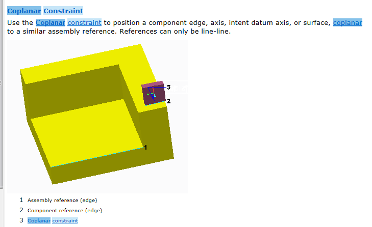
The coplanar constraint applies to two edges. It forces them on the same plane, but not coincident. I hadn't heard of it before and I'm not sure how I'd use it.
From the help (I searched for "coplanar constraint"):
[cid:image002.png@01D04B7D.3EB440A0]
--
The coplanar constraint applies to two edges. It forces them on the same plane, but not coincident. I hadn't heard of it before and I'm not sure how I'd use it.
From the help (I searched for "coplanar constraint"):
[cid:image002.png@01D04B7D.3EB440A0]
--
Feb 18, 2015
05:21 PM
- Mark as New
- Bookmark
- Subscribe
- Mute
- Subscribe to RSS Feed
- Permalink
- Notify Moderator
Please log in to access translation
Feb 18, 2015
05:21 PM
My initial thought to locate this subassembly was to create a saved analysis
measurement in the top assembly between the two faces, and then assemble the
subassembly using the plane in the subassembly offset from one of the two
faces. Once this has been done, you could create an assembly level
relationship so that the distance that the assembly is offset from the face
was half of the distance of the saved analysis feature.
Just something to ponder.
Scott Schultz
Principal Consultant
3D Relief Inc.


