Community Tip - Want the oppurtunity to discuss enhancements to PTC products? Join a working group! X
- Community
- Creo+ and Creo Parametric
- 3D Part & Assembly Design
- Re: dxf_export settings
- Subscribe to RSS Feed
- Mark Topic as New
- Mark Topic as Read
- Float this Topic for Current User
- Bookmark
- Subscribe
- Mute
- Printer Friendly Page
dxf_export settings
- Mark as New
- Bookmark
- Subscribe
- Mute
- Subscribe to RSS Feed
- Permalink
- Notify Moderator
dxf_export settings
We have a customer that requires that all AuroCAD DWG files have cetrain layer named per their list, same goes for color and linetypes. I have managed to make color and linetypes show up correct in DWG file. Only problem left is that I cannot force Creo to export layers per my settings (deja vu anyone).
What I did so far is the following:
I set "intf_out_layer" to "part_layer"
I set "intf2d_out_dxf_mapping_file" to "dxf_export.pro" file
Here is the dxf_export.pro file:
| map_color | BACKGROUND_COLOR | 186 |
| map_color | DIMMED_COLOR | 9 |
| map_color | LETTER_COLOR | 2 |
| map_color | HIGHLIGHT_COLOR | 2 |
| map_color | EDGE_HIGHLIGHT_COLOR | 2 |
| map_color | GEOMETRY_COLOR | 3 |
| map_color | HIDDEN_COLOR | 6 |
| map_color | SHEETMETAL_COLOR | 7 |
| map_color | CURVE_COLOR | 7 |
| map_color | VOLUME_COLOR | 7 |
| map_color | SECTION_COLOR | 135 |
| map_color | PRESEL_HIGHLIGHT_COLOR | 7 |
| map_color | SELECTED_COLOR | 7 |
| map_color | SECONDARY_SELECTED_COLOR 7 | |
| map_color | PREVIEW_GEOM_COLOR | 7 |
| map_color | SECONDARY_PREVIEW_COLOR 7 | |
| map_color | DATUM_COLOR | 4 |
| map_color | QUILT_COLOR | 2 |
| map_layer | DXF_AXIS | CEN |
| map_layer | DXF_CONTINUOUS_LINE | OBJ |
| map_layer | DXF_HIDDEN_LINE | HID |
| map_layer | DXF_DIMENSION | DIMS |
| map_layer | DXF_TEXT | DIMS |
| map_layer | DXF_HATCHING | HATCH |
| map_layer | DXF_TABLE | DIMS |
| map_layer | DXF_BALLOON | DIMS |
| map_layer | DXF_FORMAT | DIMS |
| map_line_style solidfont | bylayer |
| map_line_style phantomfont | PHANTOM |
| map_line_style ctrlfont | CENTER |
| map_line_style hiddenfont | HIDDEN |
| map_line_style bylayerfont | bylayer |
| map_line_style dashfont | bylayer |
| map_line_style ctrlfont_s_l | bylayer |
| map_line_style ctrlfont_s_s | bylayer |
| map_line_style ctrlfont_l_l | bylayer |
| map_line_style dashfont_s_s | bylayer |
| map_line_style phantomfont_s_s | phantom |
| map_line_style ctrlfont_mid_l | bylayer |
| map_font | font | simplex.shx |
| map_font | filled | bigfont.shx |
| !map_font | isofont | arial.ttf |
| map_font | isofont | isocp.shx |
And this is what I get:

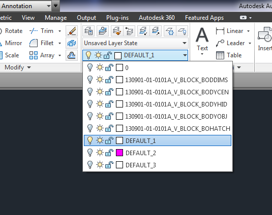
As you can see, Creo exported layers and added part number names in front of map_layer names. This is because "intf_out_layer" is set to "part_layer". There are also some of the layer named DEFAULT_1, 2 and 3 which have entities that are not specified in dxf_export.pro file. This is my guess.
I found setting "intf_out_layer_rename_table" but I could not find anything on internet on what this is and how to use it.
So, is there any additional settings that I should set to get layers as set per dxf_export.pro file? Also, what other map_layer values I am missing in this file?
Thank you in advance.
P.S. I have one more problem. Although entities are placed in right layer, object color is set to particular color instead of ByLayer, but I think I can/will solve this in AutoCAD. Is it possible to assign color of layer in dxf_export.pro file?
- Labels:
-
2D Drawing
- Mark as New
- Bookmark
- Subscribe
- Mute
- Subscribe to RSS Feed
- Permalink
- Notify Moderator
I might suggest that a client who is this particular also has a routine that assures compliance. Maybe they have a script that can do this once the DXF is opened in their system.
As for the default names, what about renaming them to one that is used? If nothing else, you could just remove these lines from the DXF file. You will likely need Autocad to confirm your output files. If you simply import it back to Creo, you might just get more "artifacts" than the file brings in.
- Mark as New
- Bookmark
- Subscribe
- Mute
- Subscribe to RSS Feed
- Permalink
- Notify Moderator
Customer does have verification software and every print has to pass the check. Their software, or LISP program does not fix anything.
- Mark as New
- Bookmark
- Subscribe
- Mute
- Subscribe to RSS Feed
- Permalink
- Notify Moderator
Nice. So, the only layers they want are CEN, OBJ, HID, DIMS and HATCH?
Do they want to be able to print from these DWG files exported from Creo?
I actually have to do something pretty similar, and I do that with a LISP routine in BricsCAD.
- Mark as New
- Bookmark
- Subscribe
- Mute
- Subscribe to RSS Feed
- Permalink
- Notify Moderator
There are some others, but I do not have them in my prints. I will be using their title block and our geometry with given layers.
- Mark as New
- Bookmark
- Subscribe
- Mute
- Subscribe to RSS Feed
- Permalink
- Notify Moderator
Does anyone know how to make a layer in drawing mode that has all hidden lines? Same question goes for layer with solid lines? What fiter rule I should use?
- Mark as New
- Bookmark
- Subscribe
- Mute
- Subscribe to RSS Feed
- Permalink
- Notify Moderator
Ok, Danilo.
If you don't convert all the drawing views to drawing entities, then you won't be able to add their hidden lines to a specific layer.
Actually, I'd like to stop you right there, and tell you that dimensions can't be converted to draft entities. So you will be stuck with those going to ACAD layer "0" as long as you have to set the config intf_out_layer set to none.
Back when I had to solve this I tried to figure out the layer rule as well, and couldn't find any.
Is your customer gonna print from the ACAD drawings?
- Mark as New
- Bookmark
- Subscribe
- Mute
- Subscribe to RSS Feed
- Permalink
- Notify Moderator
Jakub,
I do not want to change dimensions to draft entities. Actually, I managed to place all dimesnsions, tables and notes on one layer. Customer's request is that dimensions MUST be associative, not draft entities.
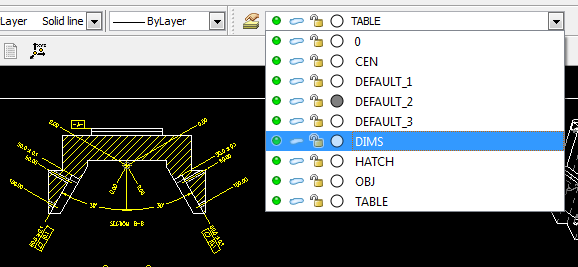
DIMS layer shown:

DIMS layer hidden:

Customer has excell spreadsheet that pulls data from print's titleblock. Customer uses these DWG prints to print them out.
- Mark as New
- Bookmark
- Subscribe
- Mute
- Subscribe to RSS Feed
- Permalink
- Notify Moderator
Pretty demanding customer.
I use to just break all the entities in BricsCAD/AutoCAD, but I would like to figure out how to avoid that, cause these DWG files tend to get pretty large then. Well, I know there is no other way.
Have you got drawing layers that take all the dims, tables or notes by a rule?
The thing about printing from DWG files exported from Pro/E is that you won't be able to set the coloring scheme for printing in ACAD (via *.ctb file).
You will have trouble with drawing printing in yellow, and other colors.
https://www.synthx.com/tom/sy_tip_0010.htm
I think those layers named DEFAULT_1, DEFAULT_2 and DEFAULT_3 could be deleted using LISP.
- Mark as New
- Bookmark
- Subscribe
- Mute
- Subscribe to RSS Feed
- Permalink
- Notify Moderator
Dveljkovic,
Can you please be more explicit how you managed to map_layer to DIMS / HATCH etc i'm still messing up with this for more than 5 days...
Thanks.
- Mark as New
- Bookmark
- Subscribe
- Mute
- Subscribe to RSS Feed
- Permalink
- Notify Moderator
Jakub,
Is it possible in CREO drawing to filter all hidden lines and place them in HID (hidden) layer? I am trying to minimize work that has to be done to comply with customer's requirements.
- Mark as New
- Bookmark
- Subscribe
- Mute
- Subscribe to RSS Feed
- Permalink
- Notify Moderator
Nope Danilo,
You wont be able to assign them to a layer if you don't convert the views to draft entities first.
Then also you propably won't be able to figure out how to assign just the dashed lines to a specific layer by a rule. As far as I remember you can only assign all the straight lines to a layer, no matter if they are continous or dashed.
Btw I found desc for that config.pro option mentioned above
- Mark as New
- Bookmark
- Subscribe
- Mute
- Subscribe to RSS Feed
- Permalink
- Notify Moderator
Jacub, just to be clear enough, when I asked this: "Does anyone know how to make a layer in drawing mode that has all hidden lines? Same question goes for layer with solid lines? What fiter rule I should use?" I was refering to CREO drawing mode, not drawing mode in Autocad.
- Mark as New
- Bookmark
- Subscribe
- Mute
- Subscribe to RSS Feed
- Permalink
- Notify Moderator
Danilo, Jakub was refering to Creo drawing mode. You cannot manually assign them to a layer unless the views in Creo are converted to draft entities.
There is no linestyle filter available, so what you ask for is not possible**. In relation to models, it makes no sense as a particular item can be both hidden and visible, depending on the view. While layer status can be view dependent, layer contents are not.
DXF is a text file format, so simple name changes may be done there, or an intermediate use of AutoCAD or other DXF compatible editor could work.
**As usual, I'm willing to be proven wrong. I've looked for this particular feature for a while, just not in relation to DXF.
- Mark as New
- Bookmark
- Subscribe
- Mute
- Subscribe to RSS Feed
- Permalink
- Notify Moderator
David,
Line can be hidden or visible on two separate views. But, based on layers settings, I should be able to assign them depending on their status and that should be automatically done afterwards. So, if line changes from solid to hidden, line goes to HIDDEN layer and vice versa. If Creo can do this when file is exported to DWG i do not understand why I cannot do it the same way.
- Mark as New
- Bookmark
- Subscribe
- Mute
- Subscribe to RSS Feed
- Permalink
- Notify Moderator
Jakub, I have found out that this setting has nothing to do with exporting DWG files from Creo:
- Mark as New
- Bookmark
- Subscribe
- Mute
- Subscribe to RSS Feed
- Permalink
- Notify Moderator
Ok, still a nice find.
Btw I perfectly understood what you've meant, Danilo, I did talk about Creo drawing mode when mumbling about draft entities. I wish there was a way to do what you want just in Creo as a whole, but sadly there's not.
I'll make some pictures tommorow at work of prints from ACAD, and then post them here so you can understand why I'm still going on about prints from DWG files, and also the message about yellow entities.
Anyway, just to clear things up for now. To convert a view to draft entities select the view --> then Layout tab --> then Edit dropdown --> and finally Convert to Draft Entities. After choosing one of the two options in menu managers, the whole view(s) will turn into something like a non-parametric sketches, sort of like pile of entities that you can edit or delete independently.
Of course, you will have to switch to Sketch tab first to be able to select these entities.
If you convert all the views to draft entities, and have a look at the drawing tree on the left. You will see that on your sheet there is a bunch of lines, arcs, splines, etc. You have to stay on Sketch tab to see these.
You can select them all from there at once, and manually assign them to a layer. But this drawing tree does not make any difference between for instance solid lines, tangent lines, hidden lines. The search tool or possibly a layer rule does not recognize the differences between these lines either.
With LISP in ACAD you can select anything, based on color, linestyle, thickness, layer name, and then have it assigned to a layer there, which you can also create with the same LISP upfront.
I have no idea how much you know from AutoCAD, but I could show you how to do that if you give me your email in a PM.
- Mark as New
- Bookmark
- Subscribe
- Mute
- Subscribe to RSS Feed
- Permalink
- Notify Moderator
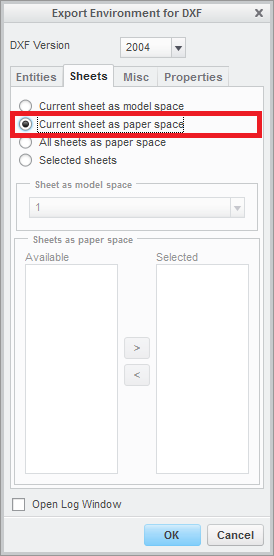
Hello 2 all. I have some questions about dxf export settings.
I need to add this option to my config.pro by default, but i don't seen this option in option list.

To check this option creo doing:
mapkey(continued) ~ Select `export_2d_dlg` `ExportOptions_Tab` 1 `Sheets_Layout`;\
mapkey(continued) ~ Select `export_2d_dlg` `SheetOpt_Group` 1 `current_paper`;


