
Turn on suggestions
Auto-suggest helps you quickly narrow down your search results by suggesting possible matches as you type.
Showing results for
Please log in to access translation
Turn on suggestions
Auto-suggest helps you quickly narrow down your search results by suggesting possible matches as you type.
Showing results for
Community Tip - You can subscribe to a forum, label or individual post and receive email notifications when someone posts a new topic or reply. Learn more! X
- Community
- Creo+ and Creo Parametric
- 3D Part & Assembly Design
- Re: hole call out help
Translate the entire conversation x
Please log in to access translation
Options
- Subscribe to RSS Feed
- Mark Topic as New
- Mark Topic as Read
- Float this Topic for Current User
- Bookmark
- Subscribe
- Mute
- Printer Friendly Page
hole call out help
May 13, 2016
02:53 PM
- Mark as New
- Bookmark
- Subscribe
- Mute
- Subscribe to RSS Feed
- Permalink
- Notify Moderator
Please log in to access translation
May 13, 2016
02:53 PM
hole call out help
Greetings:
I'm really struggling to understand Creo's drawing module and one of the issues is hole callout. I was told that the drawing mod. does have that ability and you have to use 'Show Model Annotation" weird but okay. So I found out a how have hole call out show but the callout is not what I was expecting. Need some help on this been at it for 1/2 cay and still can figure it out.
This thread is inactive and closed by the PTC Community Management Team. If you would like to provide a reply and re-open this thread, please notify the moderator and reference the thread. You may also use "Start a topic" button to ask a new question. Please be sure to include what version of the PTC product you are using so another community member knowledgeable about your version may be able to assist.
Solved! Go to Solution.
Labels:
- Labels:
-
2D Drawing
ACCEPTED SOLUTION
Accepted Solutions
Nov 16, 2021
11:15 AM
- Mark as New
- Bookmark
- Subscribe
- Mute
- Subscribe to RSS Feed
- Permalink
- Notify Moderator
Please log in to access translation
Nov 16, 2021
11:15 AM
To close this community thread on Hole Callout Format
Summary of the exchanges and proposed solution, also summarized in article CS28399:
- Default callout for Standard holes can be customized in the CALLOUT_FORMAT section of associated .hol file, located in the <Creo Installation>\Common Files\text\hole folder:
- For example C:\Program Files\PTC\Creo 8.0.0.0\Common Files\text\hole
- The configuration option hole_parameter_file_path can be used to set the location of custom .hol files
- Under the CALLOUT_FORMAT section you can use different tokens that represent parameters or symbols, for example &DIAMETER that represents the Drill Diameter or <ctrl-a>v<ctrl-b> for the counterbore symbol
- A list of tokens can be reviewed in the Creo Help Center, like here for Creo 8.0 (note that some parameters may not be applicable for previous releases).
- This section will apply to all Hole types, so unwanted information displayed for some configurations:
- If some tokens are not required when the Hole state changes (eg adding a Countersink or setting the Thread depth Through all) you can create a table in a new DEFAULT_CALLOUT_FORMAT_DATA section at the bottom of the hole chart file.
- The different callouts can be defined for each combination.
- Refer again to Creo Help center here for more details
- Specific examples are discussed in the different replies oh this thread
29 REPLIES 29
May 13, 2016
10:53 PM
- Mark as New
- Bookmark
- Subscribe
- Mute
- Subscribe to RSS Feed
- Permalink
- Notify Moderator
Please log in to access translation
May 13, 2016
10:53 PM
PTC Creo Parametric uses a lot of lookup tables to come up with parameter names. Some of these are managed internally which makes following a particular parameter (variable) hard to follow or use at will.
One of the lookup table sets are the hole tables. They have the text version of the text that will show up in the dialog box for hole annotation.
Sometimes it is worth the time investment to make the tables do what you want. For me, this isn't the case as I have many clients all wanting their own. I simply create notes with the annotation I require for each client. It is still associative if I build the note using available parameters.
Word of caution if you go changing Creo system level files... these are easily lost in a software update. Either point your config.pro to a location outside the Creo folder structure or save the library to a backup location and remember to replace them when the updates occur.
May 16, 2016
08:03 AM
- Mark as New
- Bookmark
- Subscribe
- Mute
- Subscribe to RSS Feed
- Permalink
- Notify Moderator
Please log in to access translation
May 16, 2016
08:03 AM
Is it this table?

May 16, 2016
08:15 AM
- Mark as New
- Bookmark
- Subscribe
- Mute
- Subscribe to RSS Feed
- Permalink
- Notify Moderator
Please log in to access translation
May 16, 2016
08:15 AM
Hi,
Hole definition files are text files with .hol extension in hole subdirectory.
In my installation it is C:\PTC\Creo2_M070\Creo 2.0\Common Files\M070\text\hole directory
MH
Martin Hanák
May 16, 2016
11:26 AM
- Mark as New
- Bookmark
- Subscribe
- Mute
- Subscribe to RSS Feed
- Permalink
- Notify Moderator
Please log in to access translation
May 16, 2016
11:26 AM
Martin-
I located the file, but I don't know what to do next. Can you or someone walk me through this?
Thxs
May 15, 2016
03:14 AM
- Mark as New
- Bookmark
- Subscribe
- Mute
- Subscribe to RSS Feed
- Permalink
- Notify Moderator
Please log in to access translation
May 15, 2016
03:14 AM
The parameters used for the hole note are the columns found in hole tables. The hole note itself may include more parameters than what you want as the note is formated so that it displays the relavent parameters depending on whether you are defining an English or metric standard thread. Try looking up hole table parameters in the help, it lists the parameters for each thread type. The note itself is defined in the hole tables. For symbols, such as the depth symbol, you need to determine the ASCII code to be used.
May 15, 2016
06:51 PM
- Mark as New
- Bookmark
- Subscribe
- Mute
- Subscribe to RSS Feed
- Permalink
- Notify Moderator
Please log in to access translation
May 15, 2016
06:51 PM
I usually don't remember what's relavent either so I use control "x" to cut after maybe &STD_HOLE. Then check the drawing and go back and add part of what you cut if missing something and/or if good then just add the depth symbol with the "d" number for the depth dimension in the part. It gets me there, wish ptc made that easier in creo Also the next holes are easier once you get the hang of it.
May 16, 2016
08:32 AM
- Mark as New
- Bookmark
- Subscribe
- Mute
- Subscribe to RSS Feed
- Permalink
- Notify Moderator
Please log in to access translation
May 16, 2016
08:32 AM
Attached is part of the default UNC table and the reference to the help documentation as to what parameters are used:
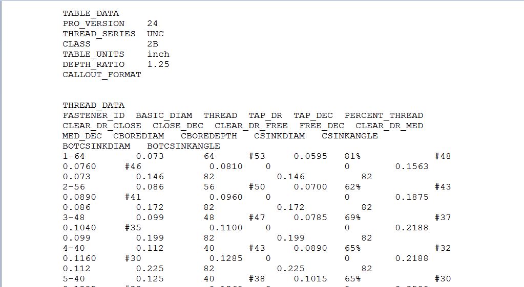
You specify the parameters you want below the CALLOUT_FORMAT.
May 16, 2016
08:46 AM
- Mark as New
- Bookmark
- Subscribe
- Mute
- Subscribe to RSS Feed
- Permalink
- Notify Moderator
Please log in to access translation
May 16, 2016
08:46 AM
Thank you.
I believe I'm pretty much in over my head on this.
May 16, 2016
12:55 PM
- Mark as New
- Bookmark
- Subscribe
- Mute
- Subscribe to RSS Feed
- Permalink
- Notify Moderator
Please log in to access translation
May 16, 2016
12:55 PM
It's very much like creating notes with displayed dimensions. I'd say first determine whether you are going edit the standard tables or create your own. If you create your own, make sure THREAD_SERIES in the header is set to what you want to appear in the thread specification drop-down of the hole feature, as this is what is shown, usually the same as the hole table file name.
Under CALLOUT_FORMAT add the parameters and other text and symbols you want to show, any column heading in the hole table file is valid. Try starting with 1 or 2 parameters such as:
&FASTENER_ID &THREAD
then try adding symbols:
<CTRL-a>x<CTRL-b> adds the depth symbol. Try different values to see what you get, I haven't found a list that shows what letter gives which symbol.
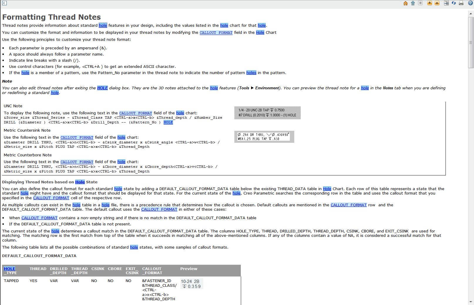
Also look up Formatting Thread Notes and there is a link to the valid parameters for use in the CALLOUT_FORMAT.
May 16, 2016
01:19 PM
- Mark as New
- Bookmark
- Subscribe
- Mute
- Subscribe to RSS Feed
- Permalink
- Notify Moderator
Please log in to access translation
May 16, 2016
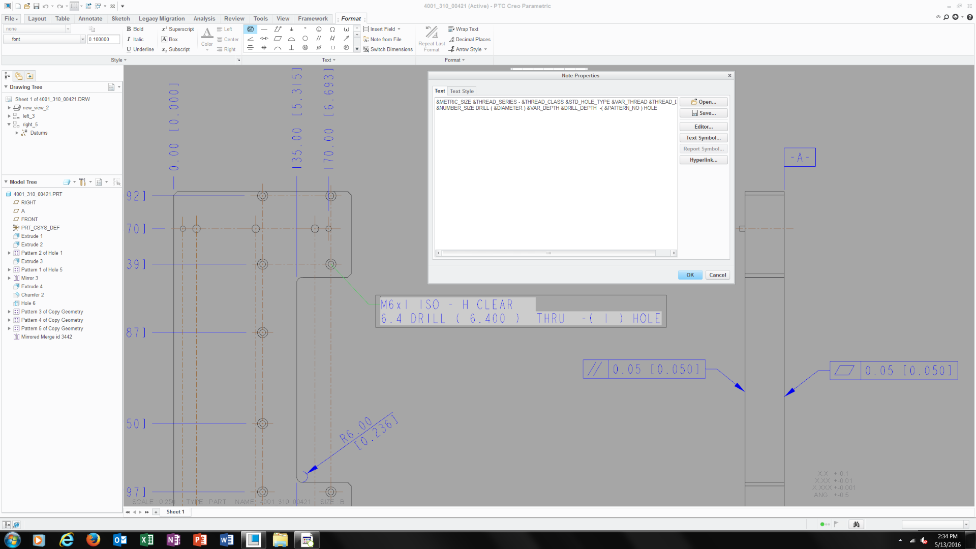
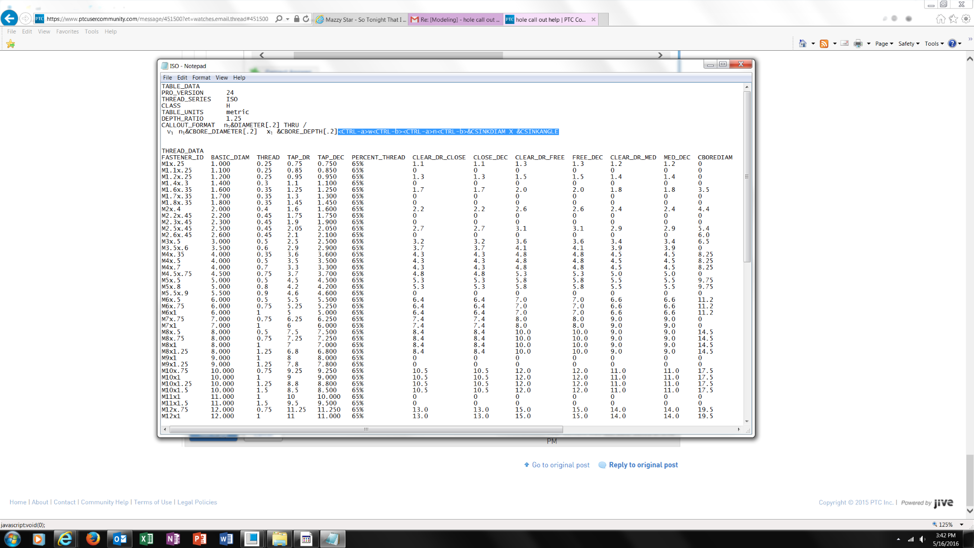
01:19 PM
Hi Kevin-
Okay some updates. 4 hours later and I figured out how to add c'bore based on the screen shot below. So my next question is if I wanted to add c-sink how would I do that? would it be the next line below?
May 16, 2016
03:26 PM
- Mark as New
- Bookmark
- Subscribe
- Mute
- Subscribe to RSS Feed
- Permalink
- Notify Moderator
Please log in to access translation
May 16, 2016
03:26 PM
You could keep the call out all on one line if you wanted the forward slash lets the system know you want something on a new line. Try:
<CTRL-a>w<CTRL-b><CTRL-a>n<CTRL-b>&CSINKDIAM X &CSINKANGLE
May 16, 2016
03:39 PM
- Mark as New
- Bookmark
- Subscribe
- Mute
- Subscribe to RSS Feed
- Permalink
- Notify Moderator
Please log in to access translation
May 16, 2016
03:39 PM
Not sure if its working do I add the text you recommend like this on the screen shot?
<CTRL-a>w<CTRL-b><CTRL-a>n<CTRL-b>&CSINKDIAM X &CSINKANGLE
May 16, 2016
03:41 PM
- Mark as New
- Bookmark
- Subscribe
- Mute
- Subscribe to RSS Feed
- Permalink
- Notify Moderator
Please log in to access translation
May 16, 2016
03:41 PM
Because I get this in the model when adding the line you mentioned. 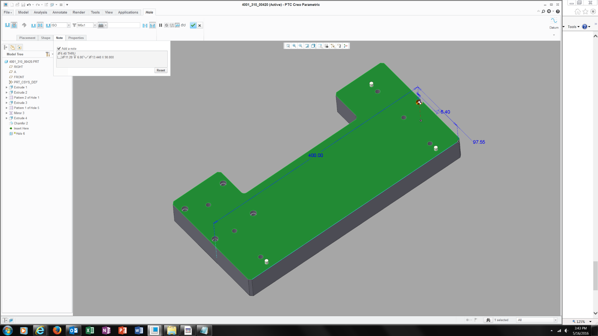
May 16, 2016
04:06 PM
- Mark as New
- Bookmark
- Subscribe
- Mute
- Subscribe to RSS Feed
- Permalink
- Notify Moderator
Please log in to access translation
May 16, 2016
04:06 PM
All you need to add is a forward slash, /, at the end of your original text and the text you added:
&CBORE_DEPTH[.2]/<CTRL-a>w<CTRL-b><CTRL-a>n<CTRL-b>&CSINKDIAM X &CSINKANGLE
May 17, 2016
09:43 AM
- Mark as New
- Bookmark
- Subscribe
- Mute
- Subscribe to RSS Feed
- Permalink
- Notify Moderator
Please log in to access translation
May 17, 2016
09:43 AM
Kevin-
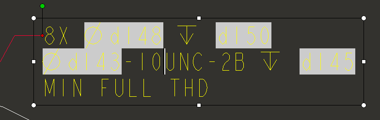
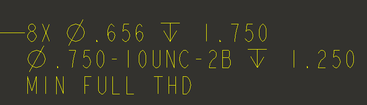
Still not working please see the screen shot below
I add the text line you mentioned
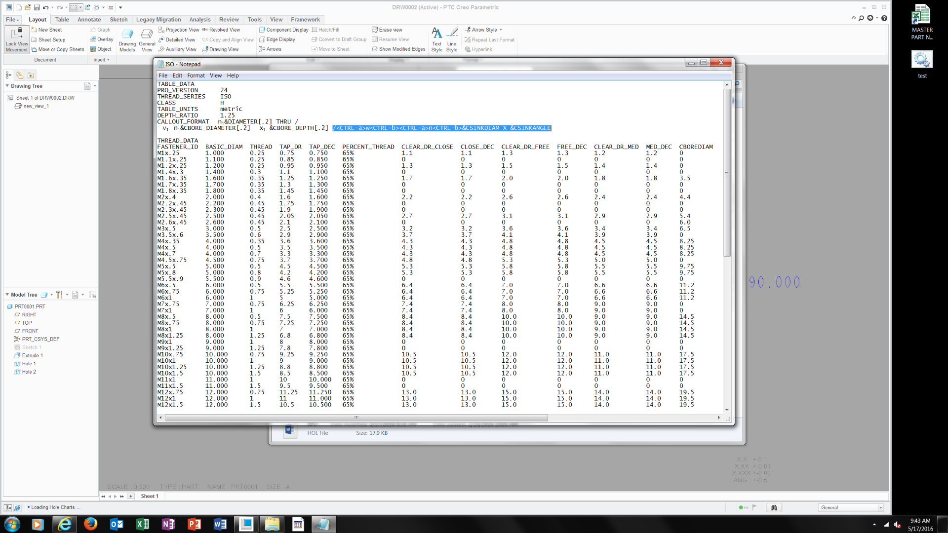
In the 3d model I get this then
Then in the drawing call out I get this.

As you can see its not correct.. suggestions?
May 17, 2016
10:40 AM
- Mark as New
- Bookmark
- Subscribe
- Mute
- Subscribe to RSS Feed
- Permalink
- Notify Moderator
Please log in to access translation
May 17, 2016
10:40 AM
Since you have a hole table file with mixed hole states add the following to the bottom of the file:
DEFAULT_CALLOUT_FORMAT_DATA
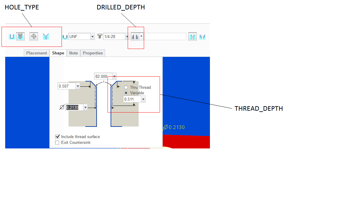
HOLE_TYPE THREAD DRILLED_DEPTH THREAD_DEPTH CSINK CBORE EXIT_CSINK CALLOUT_FORMAT
TAPPED YES VAR VAR NO NO NO &FASTENER_ID
TAPPED YES VAR VAR YES NO NO &FASTENER_ID/<CTRL-a>w<CTRL-b><CTRL-a>n<CTRL-b>&CSINKDIAM X &CSINKANGLE
TAPPED YES VAR VAR NO YES NO &FASTENER_ID/<CTRL-a>v<CTRL-b><CTRL-a>n<CTRL-b>&CBOREDIAM <CTRL-a>x<CTRL-b>&CBOREDEPTH
This should format the note based on the hole features you have.
You can remove the information from the CALLOUT_FORMAT line at the top.
May 17, 2016
11:03 AM
- Mark as New
- Bookmark
- Subscribe
- Mute
- Subscribe to RSS Feed
- Permalink
- Notify Moderator
Please log in to access translation
May 17, 2016
11:03 AM
here?
didn't work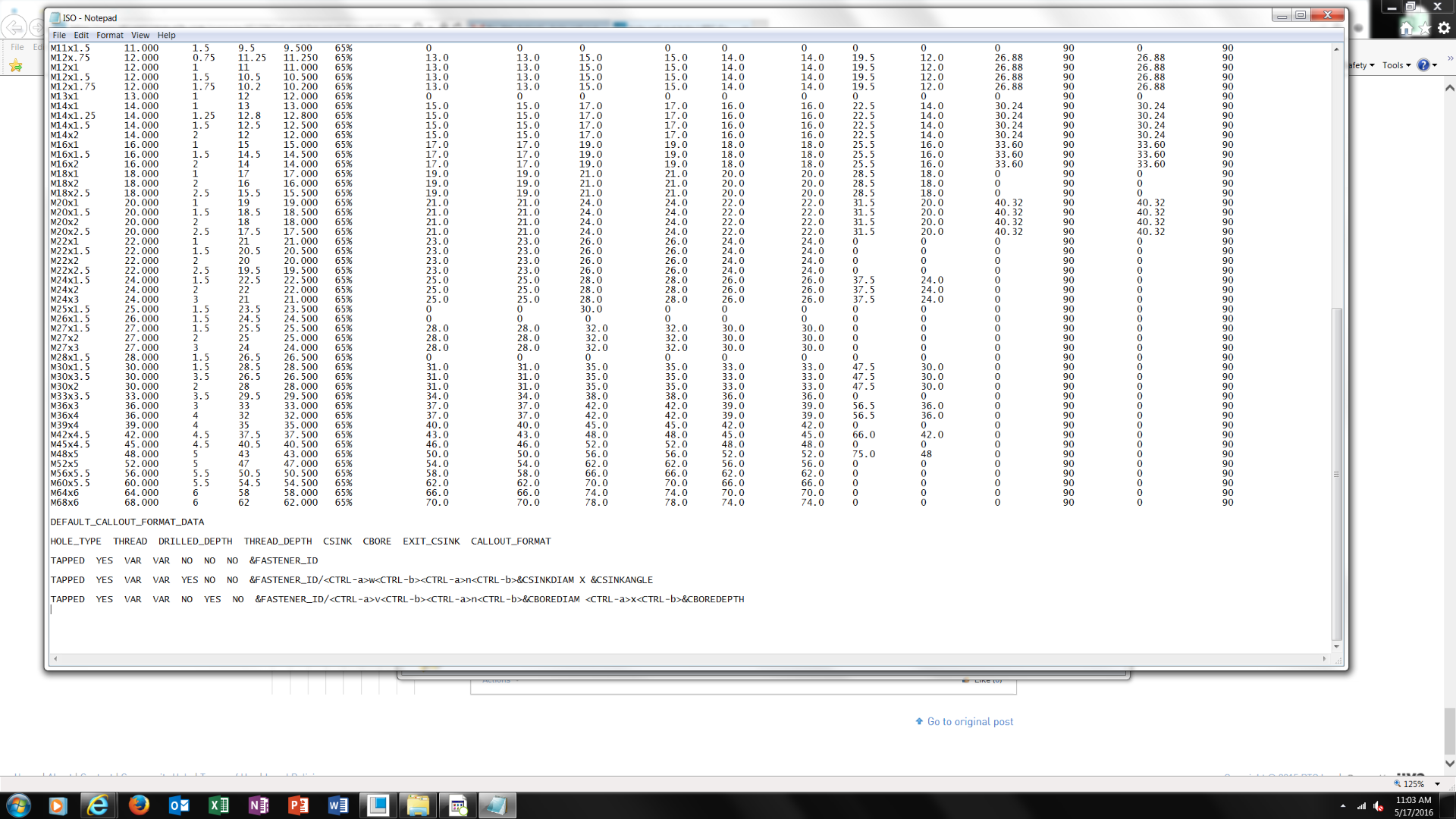
May 17, 2016
12:39 PM
- Mark as New
- Bookmark
- Subscribe
- Mute
- Subscribe to RSS Feed
- Permalink
- Notify Moderator
Please log in to access translation
May 17, 2016
12:39 PM
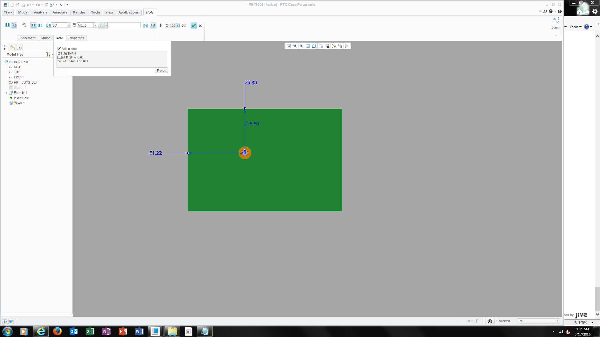
My guess is you need to try a different value for the DRILLED_DEPTH and THREAD_DEPTH. Start by changing the DRILLED_DEPTH value to THRU_ALL. These values come from how you define the hole. If these values don't match the system defaults to using the default call out.
Here is a pic of three holes with the DRILLED_DEPTH set to THRU_ALL and THREAD_DEPTH set to VAR.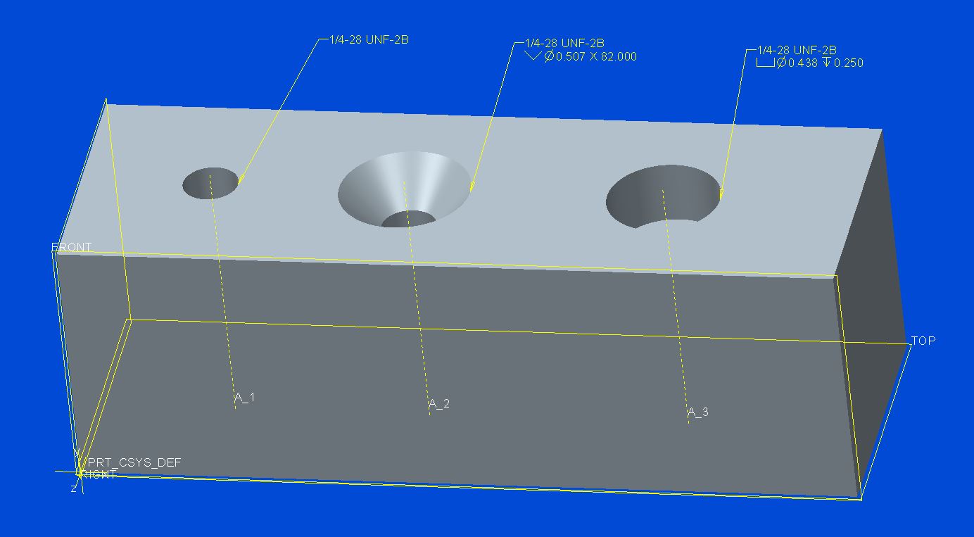
After redefining the holes in the model to be variable the default note is used.
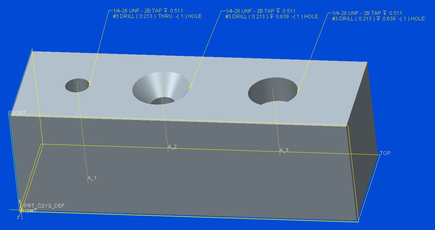
Another thing that may be causing what you are seeing is when you redefine the hole or change the note format in the *.hol file is that the notes may not automatically update, make sure to sellect reset on the Note tab and see if that updates the note.
After changing the DRILLED_DEPTH value in *.hol file to VAR for all three hole definitions, edit definition of hole 3 and reset note.
May 17, 2016
01:05 PM
- Mark as New
- Bookmark
- Subscribe
- Mute
- Subscribe to RSS Feed
- Permalink
- Notify Moderator
Please log in to access translation
May 17, 2016
01:05 PM
I still can't figure this out and its becoming very frustrating.. what other methods are there for creating a note hole on a drawing?
May 17, 2016
01:12 PM
- Mark as New
- Bookmark
- Subscribe
- Mute
- Subscribe to RSS Feed
- Permalink
- Notify Moderator
Please log in to access translation
May 17, 2016
01:12 PM
I never use the hole note. I show my dimensions and then edit the diameter dimension to show all the dimensions as I want them too.
May 17, 2016
03:54 PM
- Mark as New
- Bookmark
- Subscribe
- Mute
- Subscribe to RSS Feed
- Permalink
- Notify Moderator
Please log in to access translation
May 17, 2016
03:54 PM
If you are still interested in trying maybe this will help:
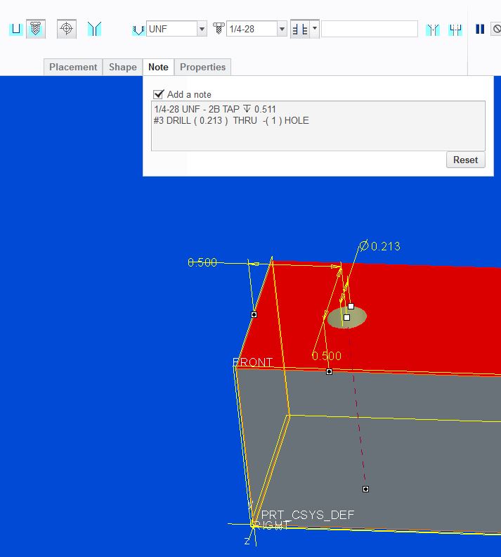
CALLOUT_FORMAT is good for a generic note for holes that always have the same features and their notes will be the same. Because you are wanting to use different features with the holes you need to use the DEFAULT_CALLOUT_FORMAT_DATA to specify the holes configuration and the parameters you want to see for use with that configuration. I'm attaching images to show where the DEFAULT_CALLOUT_FORMAT_DATA is getting information from:

If you had the following in your *.hol file:
DEFAULT_CALLOUT_FORMAT_DATA
HOLE_TYPE THREAD DRILLED_DEPTH THREAD_DEPTH CSINK CBORE EXIT_CSINK CALLOUT_FORMAT
TAPPED YES VAR VAR NO NO NO &FASTENER_ID &THREAD_SERIES-&THREAD_CLASS
you should get 1/4-28 UNF-2B from the image above.
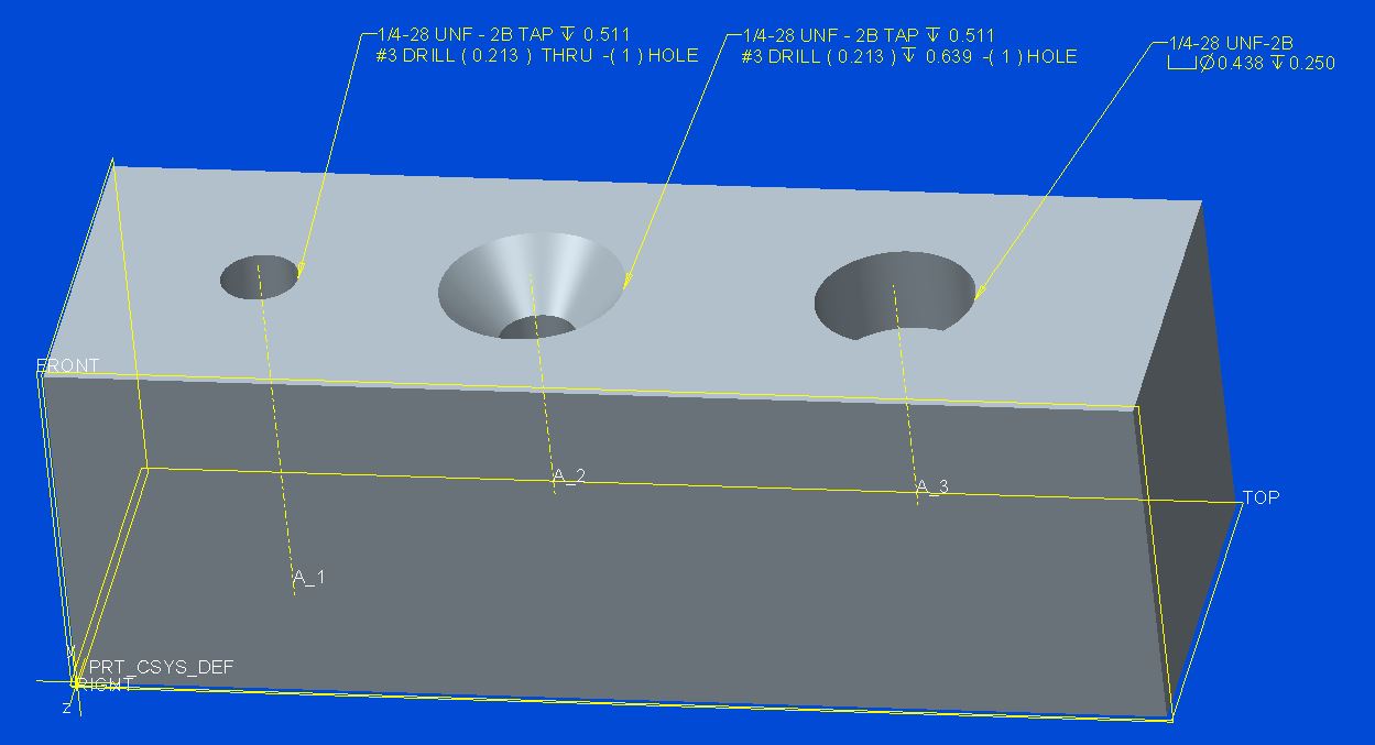
For this hole definition and the DEFAULT_CALLOUT_FORMAT_DATA above:

you should get the Creo default note. The reason being is you have deselected the thread and it is now a DRILLED hole with no thread.
If you want to change the hole to the following:
and you want to keep the note format from above you need to add another line for another hole configuration otherwise you would get the Creo default note. In the image above two things were done, the DRILLED_DEPTH was changed to THRU_ALL and a countersink was added. The new line is added and modified as shown:
DEFAULT_CALLOUT_FORMAT_DATA
HOLE_TYPE THREAD DRILLED_DEPTH THREAD_DEPTH CSINK CBORE EXIT_CSINK CALLOUT_FORMAT
TAPPED YES VAR VAR NO NO NO &FASTENER_ID &THREAD_SERIES-&THREAD_CLASS
TAPPED YES THRU_ALL VAR YES NO NO &FASTENER_ID &THREAD_SERIES-&THREAD_CLASS/<CTRL-a>w<CTRL-b><CTRL-a>n<CTRL-b>&CSINKDIAM X &CSINKANGLE
Any holes that don't conform to the two configurations shown display the Creo default note. If you want to use *.hol files and format the notes to what you want, you need a line for each hole configuration.
In the following I get the default Creo note because the hole is THRU_ALL not VAR, so the hole definition doesn't match the format data above:
To get the correct note for a thru hole the following line needs to be added to the DEFAULT_CALLOUT_FORMAT_DATA:
TAPPED YES THRU_ALL VAR NO NO NO &FASTENER_ID &THREAD_SERIES-&THREAD_CLASS
If you wanted a blind hole, you would change the DRIILED_DEPTH selection and you may or may not need to select Reset on the Note tab since it may or may not update automatically. You don't need to add a line to the *.hol file because it's already there.
If it's still not working I'd need to know the hole configuration to help with the note format or know where exactly the confusion lies. The only other thing I can say is start with one line in the DEFAULT_CALLOUT_FORMAT_DATA, change the parameters and modify the hole in various ways to see what it gives you.
May 17, 2016
05:21 PM
- Mark as New
- Bookmark
- Subscribe
- Mute
- Subscribe to RSS Feed
- Permalink
- Notify Moderator
Please log in to access translation
May 17, 2016
05:21 PM
Thanks Kevin-
I'll look into this tomorrow. In general this is far more complex than it should be compared to all other CAD systems I've ever used. A simple hole tapped or not with a depth shouldn't require all of this.. Thanks for your time and effort and I'll look into this
Thanks
May 17, 2016
05:33 PM
- Mark as New
- Bookmark
- Subscribe
- Mute
- Subscribe to RSS Feed
- Permalink
- Notify Moderator
Please log in to access translation
May 17, 2016
05:33 PM
Unfortunately, everything in Creo is like this from Welding to Cabling and Piping.
May 18, 2016
01:02 PM
- Mark as New
- Bookmark
- Subscribe
- Mute
- Subscribe to RSS Feed
- Permalink
- Notify Moderator
Please log in to access translation
May 18, 2016
01:02 PM
Yes I'm seeing this as a 4 month user of this s/w. most things taken for granted in past CAD packages are not intuitive as this one.. wonder why?
Jun 02, 2025
06:47 PM
- Mark as New
- Bookmark
- Subscribe
- Mute
- Subscribe to RSS Feed
- Permalink
- Notify Moderator
Please log in to access translation
Jun 02, 2025
06:47 PM
Creo sometimes feels like beta testing. As a mechanical designer, I find the "coding" required to do simple things so problematic that I just do it manually. I can understand if there are very specific notation a company requires but for standard threads and holes this should already be in the system. The need to edit tables and config files leads to lots of wasted hours for sure. In all my years, I have never seen any documentation on how any of this should be configured as far as location of folders and files. The prompts when saving these files assume one is a software engineer. Clearly not intended for end user modification but more for an application engineer to set up for the user. As a sole user I am left to figure it out. That being said, I source for these standard tables would be great. i will add this to a PTC feature request.
May 17, 2016
02:19 PM
- Mark as New
- Bookmark
- Subscribe
- Mute
- Subscribe to RSS Feed
- Permalink
- Notify Moderator
Please log in to access translation
May 17, 2016
02:19 PM
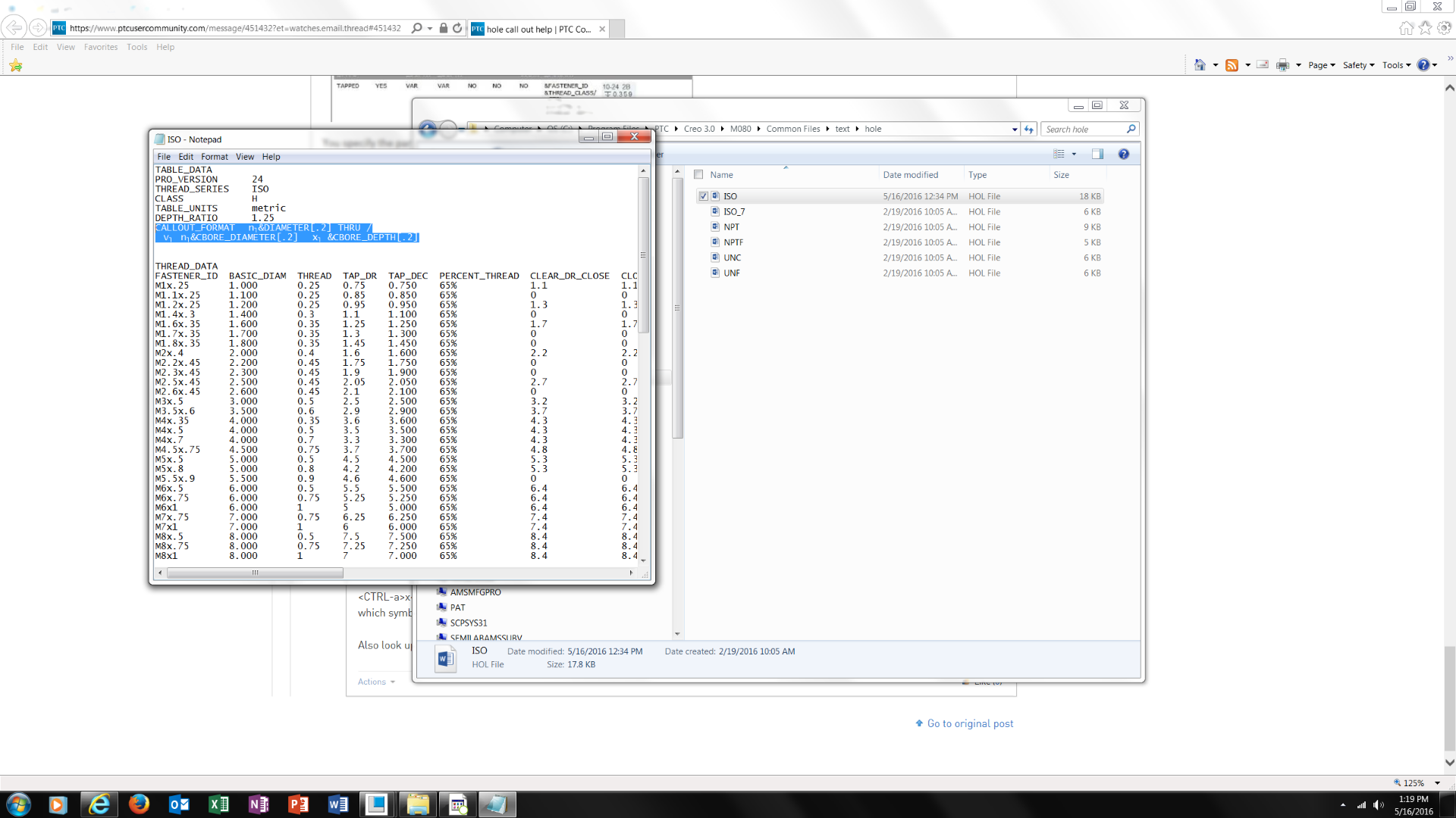
Perhaps the question I should ask is does anyone have an ISO.hole file they can send me so I can figure out how to do this?
thanks
Frank
May 17, 2016
05:30 PM
- Mark as New
- Bookmark
- Subscribe
- Mute
- Subscribe to RSS Feed
- Permalink
- Notify Moderator
Please log in to access translation
May 17, 2016
05:30 PM
Try this and see if it works. Start out with a variable depth hole adding the countersink and counterbore individually to the hole. The hole note should display the thread call out as the default and when you add a countersink or counterbore it should add the appropriate information. After you see that work change the hole type in the hole feature to THRU_ALL, when you do that the only thing that should display is the thread call out. If you add the countersink or counterbore you should only see the thread call out displayed, save your file and close. Go to the *.hol file and edit the DRILLED_DEPTH value for the desired hole to THRU_ALL, save *.hol file and re-open Creo. Edit the definition of the hole, select the Note tab, and select Reset. If the sequence was done right you should see the correct information displayed.
May 18, 2016
01:03 PM
- Mark as New
- Bookmark
- Subscribe
- Mute
- Subscribe to RSS Feed
- Permalink
- Notify Moderator
Please log in to access translation
May 18, 2016
01:03 PM
I'll look into this. I think I've cost my employer too much trying to figure something simple as this out.
Nov 16, 2021
11:15 AM
- Mark as New
- Bookmark
- Subscribe
- Mute
- Subscribe to RSS Feed
- Permalink
- Notify Moderator
Please log in to access translation
Nov 16, 2021
11:15 AM
To close this community thread on Hole Callout Format
Summary of the exchanges and proposed solution, also summarized in article CS28399:
- Default callout for Standard holes can be customized in the CALLOUT_FORMAT section of associated .hol file, located in the <Creo Installation>\Common Files\text\hole folder:
- For example C:\Program Files\PTC\Creo 8.0.0.0\Common Files\text\hole
- The configuration option hole_parameter_file_path can be used to set the location of custom .hol files
- Under the CALLOUT_FORMAT section you can use different tokens that represent parameters or symbols, for example &DIAMETER that represents the Drill Diameter or <ctrl-a>v<ctrl-b> for the counterbore symbol
- A list of tokens can be reviewed in the Creo Help Center, like here for Creo 8.0 (note that some parameters may not be applicable for previous releases).
- This section will apply to all Hole types, so unwanted information displayed for some configurations:
- If some tokens are not required when the Hole state changes (eg adding a Countersink or setting the Thread depth Through all) you can create a table in a new DEFAULT_CALLOUT_FORMAT_DATA section at the bottom of the hole chart file.
- The different callouts can be defined for each combination.
- Refer again to Creo Help center here for more details
- Specific examples are discussed in the different replies oh this thread


