Community Tip - Did you know you can set a signature that will be added to all your posts? Set it here! X
- Community
- Creo+ and Creo Parametric
- 3D Part & Assembly Design
- Re: hole position tolerance
- Subscribe to RSS Feed
- Mark Topic as New
- Mark Topic as Read
- Float this Topic for Current User
- Bookmark
- Subscribe
- Mute
- Printer Friendly Page
hole position tolerance
- Mark as New
- Bookmark
- Subscribe
- Mute
- Subscribe to RSS Feed
- Permalink
- Notify Moderator
hole position tolerance
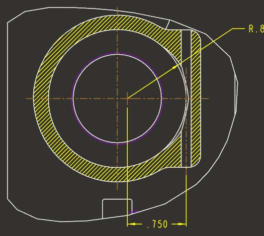
I have this hole on the right that I use for a retaining pin. My vendor has started drilling them crooked. I would like to constrain it to be parallel with the axis through the vertical center line of the larger hole.
Is there a proper geometric tolerance to use for this? The parallel tolerance does not seem to cover this.

T
This thread is inactive and closed by the PTC Community Management Team. If you would like to provide a reply and re-open this thread, please notify the moderator and reference the thread. You may also use "Start a topic" button to ask a new question. Please be sure to include what version of the PTC product you are using so another community member knowledgeable about your version may be able to assist.
- Labels:
-
Sheet Metal Design
- Mark as New
- Bookmark
- Subscribe
- Mute
- Subscribe to RSS Feed
- Permalink
- Notify Moderator
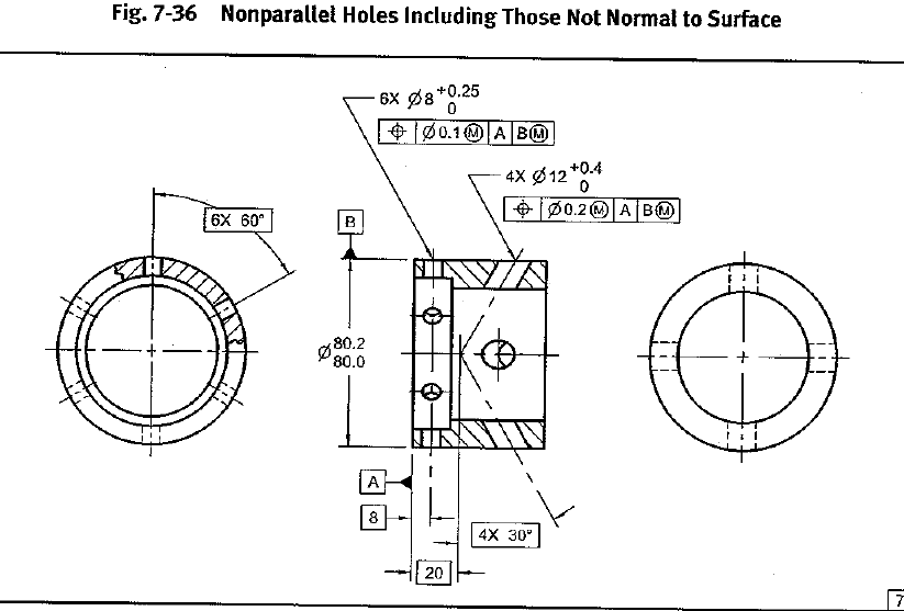
True position hold position and angularity

- Mark as New
- Bookmark
- Subscribe
- Mute
- Subscribe to RSS Feed
- Permalink
- Notify Moderator
How is the angle captured then since there is no datum through the vertical axis used for the angular dimension?
- Mark as New
- Bookmark
- Subscribe
- Mute
- Subscribe to RSS Feed
- Permalink
- Notify Moderator
You can't specify the vertical portion of a centerline as a datum.
The large hole in your part is the same as the 80.2/80.0 dimension [-B-]. The "into the page" dimension is to the [-A-] datum.
The small hole axis would have to remain within the diametrical tolerance for the entire distance which through the part which is how true position controls angularity.

- Mark as New
- Bookmark
- Subscribe
- Mute
- Subscribe to RSS Feed
- Permalink
- Notify Moderator
So would I create a datum on my diameter as well as the top surface of the part similar to the first drawing you show?
- Mark as New
- Bookmark
- Subscribe
- Mute
- Subscribe to RSS Feed
- Permalink
- Notify Moderator
You really need to look at it from a functional standpoint. Important stuff will be your datums.
On your part, since you are dimensioning to the larger hole, I'm assuming that is important to the smaller cross hole. So I would make that a datum (A or ??) and your in to plane dimension, I assume is from somewhere important so I would make that a datum (B or ??). The dimensions from those datums to your cross hole to position it would be basic dimensions. Those basic dimensions are toleranced by the GTOL and control the axis of the hole. The entire axis must stay within the tolerance as shown in the second image or interpretation, the axis of each hole stays within the tolerance zone.
It gives you the ability to inspect the length of the axis and control the drill angle, in this case 90°.
- Mark as New
- Bookmark
- Subscribe
- Mute
- Subscribe to RSS Feed
- Permalink
- Notify Moderator
And I hope someone chimes in if I'm saying something incorrectly or giving a poor explanation. Sometimes I miss important points!!
- Mark as New
- Bookmark
- Subscribe
- Mute
- Subscribe to RSS Feed
- Permalink
- Notify Moderator
Stephen is correct with having to look at if from a functional standpoint.
The creation of datums "just to create" them should be avoided unless they make sense to group a set of features together functionally.
it looks like there is more to this part. If there are datums already established, try to use them first.
you can re-order your datum importance to the feature to control specific requirements, like perpendicularity and position.
Not knowing if your part is square or round will change how one can apply proper Geometric Dimensioning and Tolerancing (GD&T). Having a round part, there is already two "datums" inherently established, but with a square part, for example, three should be created to control all directions.
To "stab" at this fundamentally, location to the cross hole should be basic, all directions. The size of the hole will be determined by your fit requirement. The positional tolerance will need to be calculated or "stacked" - what can you allow for locational deviation. this is not only how close or far you are from the assumed piece your are trying to pin (axis to axis), the fit of this assumed piece within its bore, and space within the assumed piece to allow the pin space so the part can be captured. once you know this, it will give you a good indication of what kind of "positional" location you are needing.
select the datums, if you are going to use position, according to: first; direction of the feature or "Z", then location XY or YX. Z will control perpendicularity; XY - location.
A class in ASME Y14.5 might also be helpful.
- Mark as New
- Bookmark
- Subscribe
- Mute
- Subscribe to RSS Feed
- Permalink
- Notify Moderator
Thanx Ron. That class is on my list to take this year. It is a bit confusing when you don't have all the background.
Regarding other datums and such, I guess I don't know why a datum on the other side of the part would even be relevant. There are not existing datums on this port (maybe there should be?) The issue I have is that my vendor started drilling these holes at an angle, which made the retaining pin jam into the inserted part. I need to define the pin hole location so that it will be parallel to the port hole and is center line is tangent to the bore of the port hole. I agree that a position tolerance is what should be used, but that is tied to a datum somewhere and the only thing I care about is its relation to this hole, not the rest of the part.
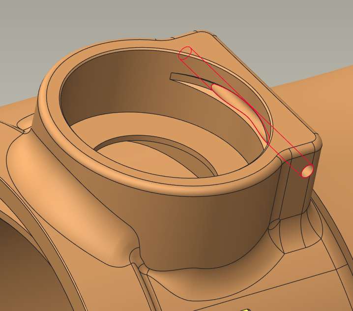
For more perspective, here is a 3D view with the pin hole in red. We place a cylindrical part in this port and then retain it with the pin. There is an o-ring at the bottom, so when the hole is off, it separates the inserted part from this 'body' and causes a leak.

- Mark as New
- Bookmark
- Subscribe
- Mute
- Subscribe to RSS Feed
- Permalink
- Notify Moderator
Anthony,
When you understand the fundamentals of GD&T, I think you will self answer your questions and perhaps understand the full ramifications of the information I provided.
Another thing I don't know is: are you making onesy twosy of these or millions. that will change dimensional schemes. I'm thinking on the lines of small quantity.
But, in the spirit of learning, every datum you set up beyond the first three have to be "qualified". If you think of it in terms of machining, you will need to do another set-up.
IF the first three datums are good enough to use for this, the establishment of additional datums is not necessary. Your stack values will determine the need.
IF new datums are needed, then by all means, establish them - but use the KISS theory (Keep It Simple Stupid) Your data from the stacks will tell you what you need to do.
Each new datum basically "resets" the stack tolerance start back to zero, essentially getting rid of excess tolerance baggage.
I do understand what you are doing. I did something similar with sleeves in a valve train that were pinned in a valve body housing for automotive transmissions and also with pressure regulators in a hydraulic circuit, pinned for easy removal.
(Looking at the design, suggest a step in the bore so you dont cut the o-ring with the pin groove)
ron
- Mark as New
- Bookmark
- Subscribe
- Mute
- Subscribe to RSS Feed
- Permalink
- Notify Moderator
From a GDT standpoint you're not controlling parallelism. Another reason for another datum would gaging, you need to be able to create a gage to check your features.
- Mark as New
- Bookmark
- Subscribe
- Mute
- Subscribe to RSS Feed
- Permalink
- Notify Moderator
It's always tough to determine a scheme that locates a feature mutual to two parts when only one part is shown, so the rest of this is just a guess and if it's wrong, there should be no complaints.
Guessing:
1) There is a face seal on the inserted part sealing against the flat surface on the bottom of the hole. This is the primary datum and the pin needs to be positioned at a certain height above that flat surface. This can be applied solely to the vertical direction.
2) The pin should not be too far from the far tangent of the hole. The mating part is not self-centering so the far tangent is going to set the position of the mating part. There is no benefit to size related tolerances, so there is no need for a positional tolerance. Just a plus-minus value that can be measured with a bore micrometer, it may require a gage pin to be installed for confirmation or a special anvil on the micrometer.
2a) Because the part has a rectangular boss, an additional constraint to make the pin hole parallel to the side of the boss would be helpful. If the boss was round there might be no functional need to limit the orientation.
3) The port needs to be located from the pin hole. This could be controlled with a profile tolerance using the pin hole as the origin datum and the bottom of the hole as a datum to refine the orientation.
4) The bottom of the hole should be perpendicular to the hole.
5) The bottom of the o-ring groove should be perpendicular to the cylinder surface of the mating part.
6) The end surface of the mating part should be located from the bottom of the o-ring groove.
7) The pin groove in the mating part should be positioned from the bottom of the o-ring groove, in that direction alone.
😎 The pin groove in the mating part should be dimensioned from the far-tangent of the mating part.
The drawing is not a process method description, it is to confirm the part is made correctly and will be useful. Trying to locate the pin hole based on the port location will be very difficult and, because the pin is what controls the positioning of this part to the next, a useless detour.
- Mark as New
- Bookmark
- Subscribe
- Mute
- Subscribe to RSS Feed
- Permalink
- Notify Moderator
You might want to try "PROJECTED TOLERANCE ZONE".


