
Turn on suggestions
Auto-suggest helps you quickly narrow down your search results by suggesting possible matches as you type.
Showing results for
Turn on suggestions
Auto-suggest helps you quickly narrow down your search results by suggesting possible matches as you type.
Showing results for
Community Tip - Did you get an answer that solved your problem? Please mark it as an Accepted Solution so others with the same problem can find the answer easily. X
- Community
- Creo+ and Creo Parametric
- 3D Part & Assembly Design
- RE: mechanica - assemblies
Options
- Subscribe to RSS Feed
- Mark Topic as New
- Mark Topic as Read
- Float this Topic for Current User
- Bookmark
- Subscribe
- Mute
- Printer Friendly Page
mechanica - assemblies
Aug 10, 2009
04:20 PM
- Mark as New
- Bookmark
- Subscribe
- Mute
- Subscribe to RSS Feed
- Permalink
- Notify Moderator
Aug 10, 2009
04:20 PM
mechanica - assemblies
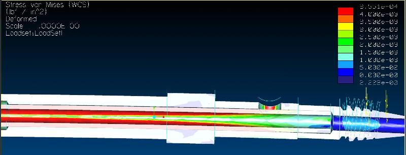
I'm trying to do a fairly simple bending analysis of an assembly. The assembly consists, basically, of two tubes. One fits snuggly (but not press fit) inside the other. The outside tube is PEEK (polyetheretherketone - a sort of plastic) and the inside tube is 316 steel. The steel tube inserts to about 80% of the length of the PEEK tube, so about 20% of the PEEK tube's length is not supported by the steel... sort of cantelevered. I want to fix the end of each tube in 6dof, and then apply a bending load to the free end of the catelevered section of the PEEK tube. The PEEK tubes are failing near where the steel ends, and we want to see what sort of load produces yield stresses & where they are localized. I've attached a screenshot of the setup from Mechanica. The steel tube is outlined in red. Whenever I run this analysis, the PEEK tube bends and the steel tube remains unloaded. 10% Scaled deformation shows the PEEK tube bent and the steel tube straight - poking out through the PEEK tube, and the stresses on the PEEK tube are localized where they would be without the steel tube present. So I assume I'm not constraining this properly, but I don't know how to get it right. I've read through much of the help docs, but can't figure out what sort of constraint I need to use. As it stands there is a very small but real clearance in the assembly model between the two tubes (i.e. they do not touch). Any help/advice would be greatly appreciated!
This thread is inactive and closed by the PTC Community Management Team. If you would like to provide a reply and re-open this thread, please notify the moderator and reference the thread. You may also use "Start a topic" button to ask a new question. Please be sure to include what version of the PTC product you are using so another community member knowledgeable about your version may be able to assist.
This thread is inactive and closed by the PTC Community Management Team. If you would like to provide a reply and re-open this thread, please notify the moderator and reference the thread. You may also use "Start a topic" button to ask a new question. Please be sure to include what version of the PTC product you are using so another community member knowledgeable about your version may be able to assist.
Labels:
- Labels:
-
Assembly Design
21 REPLIES 21
Aug 10, 2009
06:06 PM
- Mark as New
- Bookmark
- Subscribe
- Mute
- Subscribe to RSS Feed
- Permalink
- Notify Moderator
Aug 10, 2009
06:06 PM
There is no force(load) applied to the steel, that's the first problem I see, you need to define the part as one piece consisting of two different materials. Rick
Aug 10, 2009
07:25 PM
- Mark as New
- Bookmark
- Subscribe
- Mute
- Subscribe to RSS Feed
- Permalink
- Notify Moderator
Aug 10, 2009
07:25 PM
Thanks, but how do I do this? If I make both bodies one solid in Pro/E-std, then how do I create two sections of different materials? Or, is there a way to make mechanica treat/analyze them as one solid but still be able to address them seperately for material assignments? I thought that I read that if two solids in an assembly share a face, then Mechanica will treat them as one solid for analysis. But I couldn't get this to happen. But regardless, I don't know that I want them to be treated as one solid... the interface between the PEEK and steel is fairly low friction. Thanks again for the help...
Aug 10, 2009
07:42 PM
- Mark as New
- Bookmark
- Subscribe
- Mute
- Subscribe to RSS Feed
- Permalink
- Notify Moderator
Aug 10, 2009
07:42 PM
You have the tubs fully constrained in assy. mode and not just packaged? The load is being applied to the plastic tube in the drawing, Mechanica is not recognizing the steel, there could be a number of reasons for this, I couldn't get into it on the internet. I would have to go through some notes to tell you how to create one part out of two materials. To start, make sure everything is fully constrained in assy, it will take more than two surfaced being constrained. If that doesn't work you'll have to figure something else out.
Aug 11, 2009
01:19 PM
- Mark as New
- Bookmark
- Subscribe
- Mute
- Subscribe to RSS Feed
- Permalink
- Notify Moderator
Aug 11, 2009
01:19 PM
"Richard Giguere" wrote:
You have the tubs fully constrained in assy. mode and not just packaged?
Aug 11, 2009
02:07 PM
- Mark as New
- Bookmark
- Subscribe
- Mute
- Subscribe to RSS Feed
- Permalink
- Notify Moderator
Aug 11, 2009
02:07 PM
Okay, I found the help topic on "packaging". I also discovered the place where Mechanica tells you if a part in an assembly is fully or partially constrained. So, the steel tube was not fully constrained. Now it is, as is the PEEK tube. But I still get the same results when I run an analysis.
Aug 11, 2009
04:17 PM
- Mark as New
- Bookmark
- Subscribe
- Mute
- Subscribe to RSS Feed
- Permalink
- Notify Moderator
Aug 11, 2009
04:17 PM
Hello Keiran Since the fully constrained method of an assy. did work, if it was me I would redefine the assy as on part(re created it as one solid piece). There is a way to assign different materials to different areas of a part, I've done it, I can't tell you off the top of my head how I did it, but it wasn't that hard. Then the part will be one solid piece and you should get a good FEA. FEA is kinda hard and I try not to get into on the net. Knowing that you got a correct result takes a lot of experience(which I don't have). have fun regards Rick
Aug 11, 2009
04:19 PM
- Mark as New
- Bookmark
- Subscribe
- Mute
- Subscribe to RSS Feed
- Permalink
- Notify Moderator
Aug 11, 2009
04:19 PM
I knew I was going to get the e and i backwards on your name...sorry about that.
Aug 11, 2009
04:25 PM
- Mark as New
- Bookmark
- Subscribe
- Mute
- Subscribe to RSS Feed
- Permalink
- Notify Moderator
Aug 11, 2009
04:25 PM
"Richard Giguere" wrote:
I knew I was going to get the e and i backwards on your name...sorry about that.
Aug 12, 2009
01:39 AM
- Mark as New
- Bookmark
- Subscribe
- Mute
- Subscribe to RSS Feed
- Permalink
- Notify Moderator
Aug 12, 2009
01:39 AM
Here is a screen shot of a part with two materials. The help files should have something on this. Hope this helps lator rick
Aug 13, 2009
11:01 AM
- Mark as New
- Bookmark
- Subscribe
- Mute
- Subscribe to RSS Feed
- Permalink
- Notify Moderator
Aug 13, 2009
11:01 AM
In Mechanica, you can split a single part into two volumes (Insert > Volume Region) and assign different materials to each volume. However, I don't think this is the best solution for your case - the assembly you have should be fine. If the two parts are of the same diameter then Mechanica will assume they are bonded. If there is a gap between the diameters, or you want to allow the parts to slip where they contact, you need to define contact regions between the parts: WF4 - Insert > Connection > Auto Detect and Create Contacts When you set up the static analysis, you will find that "Include Contacts" is selected. The analysis will take longer to run than a normal static analysis. I hope this helps.
Aug 13, 2009
01:50 PM
- Mark as New
- Bookmark
- Subscribe
- Mute
- Subscribe to RSS Feed
- Permalink
- Notify Moderator
Aug 13, 2009
01:50 PM
"Andrew Deighton" wrote:
In Mechanica, you can split a single part into two volumes (Insert > Volume Region) and assign different materials to each volume. However, I don't think this is the best solution for your case - the assembly you have should be fine. If the two parts are of the same diameter then Mechanica will assume they are bonded. If there is a gap between the diameters, or you want to allow the parts to slip where they contact, you need to define contact regions between the parts: WF4 - Insert > Connection > Auto Detect and Create Contacts When you set up the static analysis, you will find that "Include Contacts" is selected. The analysis will take longer to run than a normal static analysis. I hope this helps.
Aug 13, 2009
02:12 PM
- Mark as New
- Bookmark
- Subscribe
- Mute
- Subscribe to RSS Feed
- Permalink
- Notify Moderator
Aug 13, 2009
02:12 PM
It sounds like you are saying, if the two diameters are the same, a fully constrained assembly will work in Mechanica, but if they're not and you want them to move or have a gap you need to do the "Insert > Connection > Auto Detect and Create Contacts" before you fully constrain the assy. just curious what you mean, this new to me. Rick
Aug 13, 2009
02:15 PM
- Mark as New
- Bookmark
- Subscribe
- Mute
- Subscribe to RSS Feed
- Permalink
- Notify Moderator
Aug 13, 2009
02:15 PM
Mechanica pays no attention to how things are assembled in Pro/ENGINEER - it sees the parts as seperate bodies. The bodies are joined if they have coincident surfaces and the default connection is bonded, or you can make connections - links, bolts, contacts etc.
Aug 13, 2009
02:18 PM
- Mark as New
- Bookmark
- Subscribe
- Mute
- Subscribe to RSS Feed
- Permalink
- Notify Moderator
Aug 13, 2009
02:18 PM
If your assembly contained two gears with a gap between the teeth, you need to define contact regions between them to pass the load from one part to the other, the same in this case with the shafts, assuming there is a gap between them.
Aug 13, 2009
02:29 PM
- Mark as New
- Bookmark
- Subscribe
- Mute
- Subscribe to RSS Feed
- Permalink
- Notify Moderator
Aug 13, 2009
02:29 PM
"Andrew Deighton" wrote:
If your assembly contained two gears with a gap between the teeth, you need to define contact regions between them to pass the load from one part to the other, the same in this case with the shafts, assuming there is a gap between them.
Aug 13, 2009
02:30 PM
- Mark as New
- Bookmark
- Subscribe
- Mute
- Subscribe to RSS Feed
- Permalink
- Notify Moderator
Aug 13, 2009
02:30 PM
It makes no difference - constrain first, contacts first....
Aug 13, 2009
02:38 PM
- Mark as New
- Bookmark
- Subscribe
- Mute
- Subscribe to RSS Feed
- Permalink
- Notify Moderator
Aug 13, 2009
02:38 PM
"Andrew Deighton" wrote:
It makes no difference - constrain first, contacts first....
Aug 13, 2009
03:07 PM
- Mark as New
- Bookmark
- Subscribe
- Mute
- Subscribe to RSS Feed
- Permalink
- Notify Moderator
Aug 13, 2009
03:07 PM
"Andrew Deighton" wrote:
It makes no difference - constrain first, contacts first....
Aug 18, 2009
01:20 PM
- Mark as New
- Bookmark
- Subscribe
- Mute
- Subscribe to RSS Feed
- Permalink
- Notify Moderator
Aug 18, 2009
01:20 PM
Sorry for not updating this thread. Short story: with the contact connection defined between the two cylindrical surfaces, the simulation ran successfully. Long story: while trying to figure out a solution, I needed a quick & dirty result. So I set the o.d. of the inner tube equal to the i.d. of the outer tube, so that the two surfaces were flush (no gap). When you do this, Mechanica meshes the assembly as one solid, but still allows you to define different material properties for each part. This allowed the analysis to run successfully, without any further constraints needed (asside from those already described in my earlier posts). The problem with this solution (asside from that the dimensions were not real any more) is that the interface of these two surfaces is then assumed to be bonded (no slip). This was not realistic for my assembly. Anyway, with the contact connection inserted, it worked great, and slippage and gaps were allowed between the two surfaces, and loads were trasmitted between the two parts.
Aug 18, 2009
10:36 PM
- Mark as New
- Bookmark
- Subscribe
- Mute
- Subscribe to RSS Feed
- Permalink
- Notify Moderator
Aug 18, 2009
10:36 PM
"Kieran Coghlan" wrote:
Sorry for not updating this thread. Short story: with the contact connection defined between the two cylindrical surfaces, the simulation ran successfully. Long story: while trying to figure out a solution, I needed a quick & dirty result. So I set the o.d. of the inner tube equal to the i.d. of the outer tube, so that the two surfaces were flush (no gap). When you do this, Mechanica meshes the assembly as one solid, but still allows you to define different material properties for each part. This allowed the analysis to run successfully, without any further constraints needed (asside from those already described in my earlier posts). The problem with this solution (asside from that the dimensions were not real any more) is that the interface of these two surfaces is then assumed to be bonded (no slip). This was not realistic for my assembly. Anyway, with the contact connection inserted, it worked great, and slippage and gaps were allowed between the two surfaces, and loads were trasmitted between the two parts.
Aug 19, 2009
05:49 PM
- Mark as New
- Bookmark
- Subscribe
- Mute
- Subscribe to RSS Feed
- Permalink
- Notify Moderator
Aug 19, 2009
05:49 PM
I had both parts fully constrained in assy mode. I then constrained one end of each tube in 6dof as shown in the above images. I then defined a contact connection between the o.d. surface of the inner tube and the i.d. surface of the outer tube. That's all. In the attached image, you can see that there are varying gaps between the steel (inner) tube and the PEEK (outer) tube.

