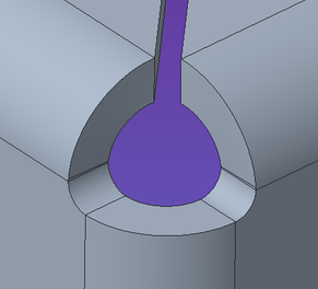
miter cut / corner releif of a chane flange bend
- Mark as New
- Bookmark
- Subscribe
- Mute
- Subscribe to RSS Feed
- Permalink
- Notify Moderator
miter cut / corner releif of a chane flange bend
Hi, trying to understand how to get what I want. While I have options, nothing seem to change when various option are chosen..
1) I made a chain flange to have a nice flange about the 2 sides of an 'L' shape.
It then makes the flange, and creates both a corner relief and a mitered cut. If I choose "closed" I get a closed off corner, which is what I believe I want. But it does give a bit of a weird shape on the flat pattern.
It also gives a gap. The end of the gap isn't really 'tangent' to the inside of the corner bend radius, which I would have expected.
Now, if I have an open corner, the gap creates a little 'tooth' on each side of the mating mitered flange edges. (See mitered.jpg) I then need to do an unbend / bend back with an extrusion cut to remove these "bits", and get a simple 45°cuts on the flat pattern.. (See miter 2 & miter 3.jpg..)
2) while I have options to vary the corner relief, nothing seems to change with options chosen. So, no idea what these do or control.
I feel I am stuck with whatever Creo is programmed to spit out..
any help or direction to a better / concise explanation on how / what these options control?
dunno really how else to explain it..
- Mark as New
- Bookmark
- Subscribe
- Mute
- Subscribe to RSS Feed
- Permalink
- Notify Moderator
If you change the 1.1*Thickness to 0 the nubs will be removed leaving only the small gap.
There is always more to learn in Creo.
- Mark as New
- Bookmark
- Subscribe
- Mute
- Subscribe to RSS Feed
- Permalink
- Notify Moderator
Hi, thanks.
No. The smallest I can enter the gap is 0.0008", I still get the nubs. (although teeny tiny!)
Unless I missed something else..
- Mark as New
- Bookmark
- Subscribe
- Mute
- Subscribe to RSS Feed
- Permalink
- Notify Moderator
I have always found the sheetmetal reliefs a bit lacking in Creo.
The small nubs are Creo trying to keep the edge perpendicular to the surface as it goes around the corner. The only way to create a "clean" relief is to create it yourself.
Unless you need a tight corner fit, to reduce stress concentrations, I would suggest this type of relief cut:
There is always more to learn in Creo.


