
Turn on suggestions
Auto-suggest helps you quickly narrow down your search results by suggesting possible matches as you type.
Showing results for
Please log in to access translation
Turn on suggestions
Auto-suggest helps you quickly narrow down your search results by suggesting possible matches as you type.
Showing results for
Community Tip - When posting, your subject should be specific and summarize your question. Here are some additional tips on asking a great question. X
Translate the entire conversation x
Please log in to access translation
Options
- Subscribe to RSS Feed
- Mark Topic as New
- Mark Topic as Read
- Float this Topic for Current User
- Bookmark
- Subscribe
- Mute
- Printer Friendly Page
sweep
Mar 12, 2016
04:15 PM
- Mark as New
- Bookmark
- Subscribe
- Mute
- Subscribe to RSS Feed
- Permalink
- Notify Moderator
Please log in to access translation
Mar 12, 2016
04:15 PM
sweep
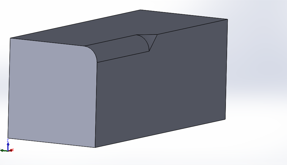
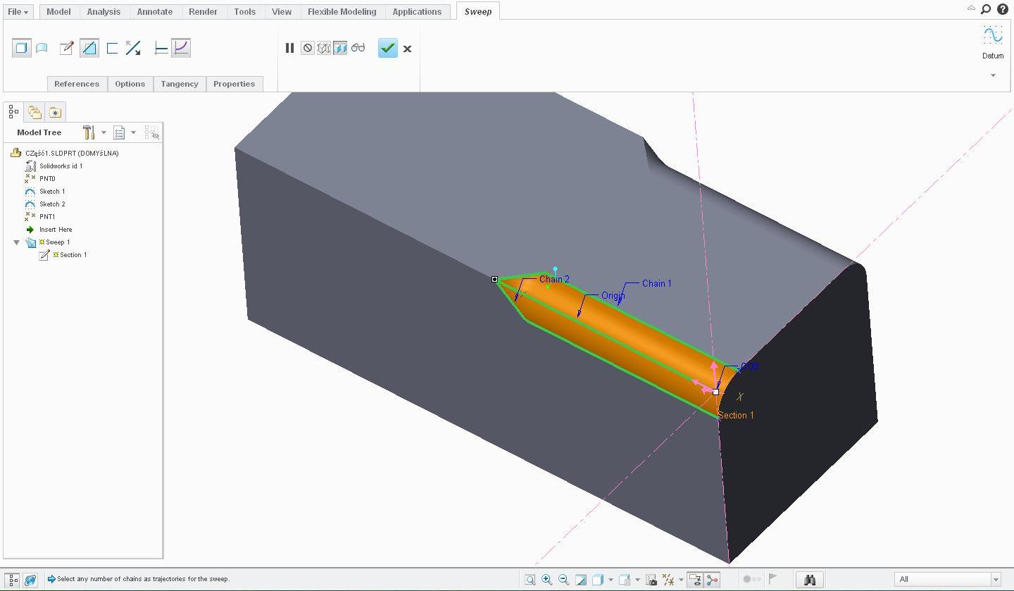
Hi I have a small problem using a sweep feature in Creo 3.0.
Using this sweep feature i can create sketch on a normal plane to trajectory line.
for example i am sending some screens what i want to do (this example i have made in solidworks)
p.s. sorry for bad englisch:p
 .
.
This thread is inactive and closed by the PTC Community Management Team. If you would like to provide a reply and re-open this thread, please notify the moderator and reference the thread. You may also use "Start a topic" button to ask a new question. Please be sure to include what version of the PTC product you are using so another community member knowledgeable about your version may be able to assist.
Labels:
- Labels:
-
General
- Tags:
- sweep
- sweep blend
41 REPLIES 41
Mar 14, 2016
08:26 AM
- Mark as New
- Bookmark
- Subscribe
- Mute
- Subscribe to RSS Feed
- Permalink
- Notify Moderator
Please log in to access translation
Mar 14, 2016
08:26 AM
Use the variable section sweep option. When defining the sketch create a relation for dimensions in the sketch (the variable "trajpar" is the trajectory from 0 to 1).
Here is a 100 mm round sweep cut followed by a shorter sweep with the relation "sd3=100-(trajpar*100)" (sd3 being the radius dimension). A carefully created relation could do it all in one feature.
There is always more to learn in Creo.
Mar 15, 2016
02:43 AM
- Mark as New
- Bookmark
- Subscribe
- Mute
- Subscribe to RSS Feed
- Permalink
- Notify Moderator
Please log in to access translation
Mar 15, 2016
02:43 AM
I do not see the sweep feature clearly on the SW version. If you attach the SW file, I can see what it is doing and do the same with Creo for you.
Mar 15, 2016
03:10 AM
- Mark as New
- Bookmark
- Subscribe
- Mute
- Subscribe to RSS Feed
- Permalink
- Notify Moderator
Please log in to access translation
Mar 15, 2016
03:10 AM
Ok. I'll do it later today
Mar 15, 2016
02:18 PM
- Mark as New
- Bookmark
- Subscribe
- Mute
- Subscribe to RSS Feed
- Permalink
- Notify Moderator
Please log in to access translation
Mar 15, 2016
02:45 PM
- Mark as New
- Bookmark
- Subscribe
- Mute
- Subscribe to RSS Feed
- Permalink
- Notify Moderator
Please log in to access translation
Mar 15, 2016
02:45 PM
There are a lot of things about SolidWorks that does some interesting things beyond what you are truly asking for.
I was able to make the same shape with a Boundary Blend but it has a pinch point. Just draw the two lines, one on the side an done on the top.
make the boundary blend with the 2 new lines to be one set, then switch to the second set and pick the common vertex of the two previous lines and the arc at the end of the round. Now change the surface merging with the round to tangent within the boundary blend.
I left the sharp point and solidified the boundary blend. With the right settings, it will remove the excess material.
And for other's looking at this, the sweep of the transition is inverses. There is no simple round feature that will do this.
Mar 15, 2016
03:09 PM
- Mark as New
- Bookmark
- Subscribe
- Mute
- Subscribe to RSS Feed
- Permalink
- Notify Moderator
Please log in to access translation
Mar 15, 2016
03:09 PM
Interesting. In SW, it is doing a rotation of an offset triangle from the axis. As a sweep in Creo, it has to use a different orientation than default. I tried a revolve cut but it won't accept the offset axis. I'll have to look at it some more to see if I can get the sweep to change the sketch orientation.

Mar 15, 2016
07:25 AM
- Mark as New
- Bookmark
- Subscribe
- Mute
- Subscribe to RSS Feed
- Permalink
- Notify Moderator
Please log in to access translation
Mar 15, 2016
07:25 AM
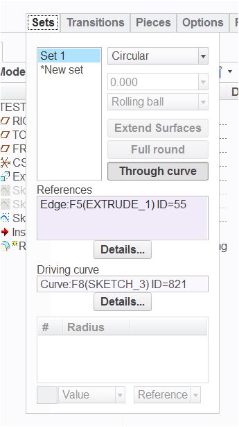
You can do this with a curve and the round feature. Create a sketched curved along one of the faces you want your curve, straight line the 3 point tangent or what shape you require. Create a round thru a curve, select the curve first, then select References and select the edge the curve will pass thru, and your done.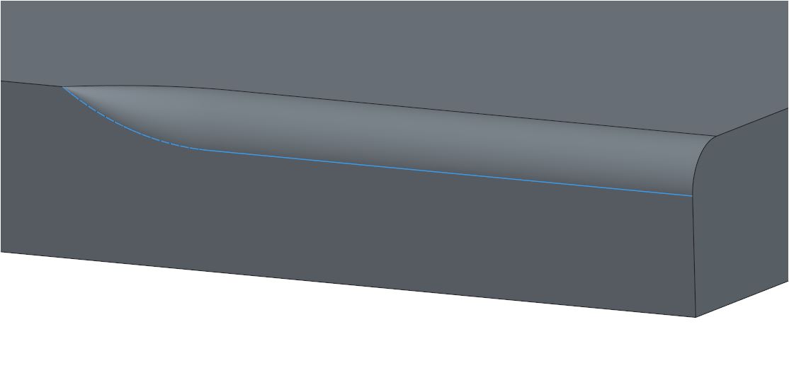
Mar 15, 2016
06:26 PM
- Mark as New
- Bookmark
- Subscribe
- Mute
- Subscribe to RSS Feed
- Permalink
- Notify Moderator
Please log in to access translation
Mar 15, 2016
06:26 PM
As always, it depends on the actual SHAPE you want. You could try a VSS using a curve on a plane thru the edge, at half the included angle to control the radius going from a value to zero. that way you can use an "S" shape at the end to make that last transition tangent to the radius dimension, to tangent to the edge.
Mar 15, 2016
08:22 PM
- Mark as New
- Bookmark
- Subscribe
- Mute
- Subscribe to RSS Feed
- Permalink
- Notify Moderator
Please log in to access translation
Mar 15, 2016
08:22 PM
The shape he is duplicating is very specific. For Creo, it might as well be one of those "3D shape sweeps". Look carefully at what SW is doing.
Mar 15, 2016
09:35 PM
- Mark as New
- Bookmark
- Subscribe
- Mute
- Subscribe to RSS Feed
- Permalink
- Notify Moderator
Please log in to access translation
Mar 15, 2016
09:35 PM
This video is what I ended up using boundary blend along a series of ribs. I could not get sweep to provide an alternate sketch plane in the required orientation.
In this case I used pattern along a spine with a redefined origin. This ensures there is no offset due to some origin conflict which you cannot resolve using an axis pattern.
I do trust that this geometry is the same as it was in SW. ...remember to set the video to HD.
Mar 15, 2016
11:31 PM
- Mark as New
- Bookmark
- Subscribe
- Mute
- Subscribe to RSS Feed
- Permalink
- Notify Moderator
Please log in to access translation
Mar 15, 2016
11:31 PM
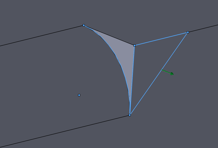
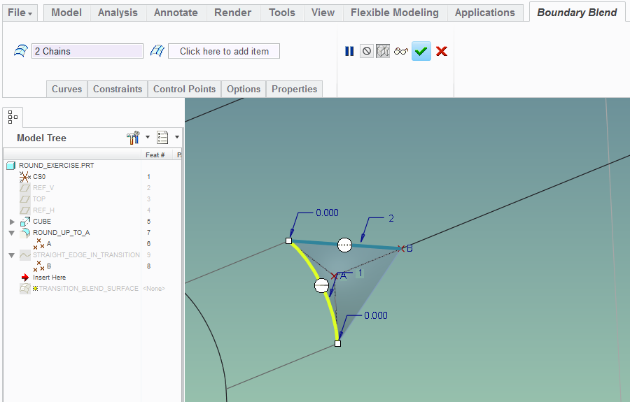
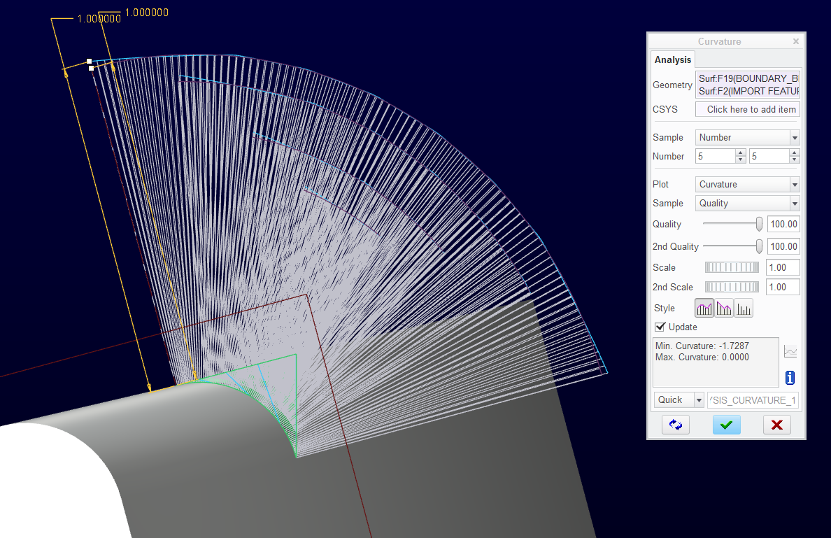
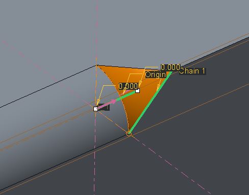
I'm curious - is it really necessary to do this complex transformation of a triangle here? It seems that only the "hypotenuse" of this triangle will be used to generate the cutting surface. This made me think that perhaps you could use a simple boundary blend as shown below (note no 2nd direction chains and also the tangency constraint on the curved edge):
This is the resulting reflection analysis:
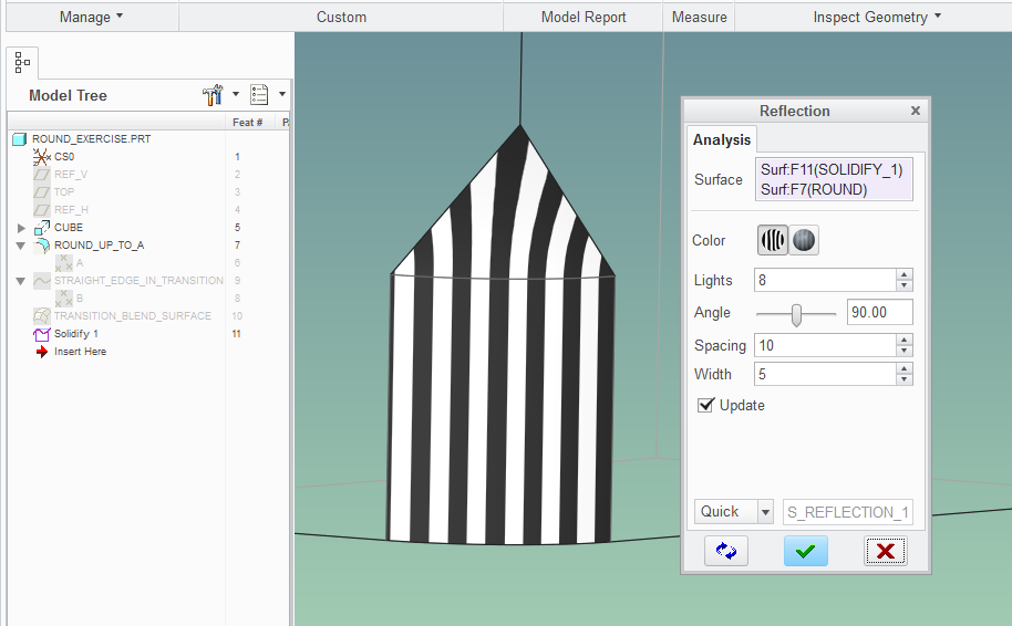
Could you tell me if this geometry is identical, or just similar to what you showed in your video?
Mar 16, 2016
12:31 AM
- Mark as New
- Bookmark
- Subscribe
- Mute
- Subscribe to RSS Feed
- Permalink
- Notify Moderator
Please log in to access translation
Mar 16, 2016
12:31 AM
Paul, you are right, the boundary blend will work with only 2 elements since the implied connection is a straight line.
One thing that remains variable in boundary blend is that there is a variable attached to the curvature of the tangent.
The simulation should be real close however.
I will save the SolidWorks file out as a step (original) and attach it after I look at Rohit's model.
Mar 16, 2016
12:37 AM
- Mark as New
- Bookmark
- Subscribe
- Mute
- Subscribe to RSS Feed
- Permalink
- Notify Moderator
Please log in to access translation
Mar 16, 2016
12:37 AM
This was output as STEP right from SolidWorks as posted above.
Mar 15, 2016
11:57 PM
- Mark as New
- Bookmark
- Subscribe
- Mute
- Subscribe to RSS Feed
- Permalink
- Notify Moderator
Please log in to access translation
Mar 16, 2016
12:32 AM
- Mark as New
- Bookmark
- Subscribe
- Mute
- Subscribe to RSS Feed
- Permalink
- Notify Moderator
Please log in to access translation
Mar 16, 2016
12:32 AM
You have to tell us how you used the VSS because I cannot get the right plane to simulate what SolidWorks did.
Mar 16, 2016
12:45 AM
- Mark as New
- Bookmark
- Subscribe
- Mute
- Subscribe to RSS Feed
- Permalink
- Notify Moderator
Please log in to access translation
Mar 16, 2016
12:45 AM
Unfortunately I only have the student version of Creo 3.0.
I think the above picture will make it clear.
Mar 16, 2016
01:15 AM
- Mark as New
- Bookmark
- Subscribe
- Mute
- Subscribe to RSS Feed
- Permalink
- Notify Moderator
Please log in to access translation
Mar 16, 2016
01:15 AM
I detected a difference so I figured out you were on a different direction.
I do not know if exact or close enough is a solution in this case.
I'm hoping someone remembers how to do an offset rotation which is what the original was.
I just data doctor to copy the original surface and specifically rotated and placed the fragment.
I used it to Solidify and kept the new surface and preserved the smaller volume.
This categorizes as "similar" 

Mar 16, 2016
01:47 AM
- Mark as New
- Bookmark
- Subscribe
- Mute
- Subscribe to RSS Feed
- Permalink
- Notify Moderator
Please log in to access translation
Mar 16, 2016
01:47 AM
I did the same with the patterned sketch/boundary blend/solidify. The second solidify fails because it leaves only a quilt.
Below is a surface analysis of the boundary blend and the original surface. This is well within the accuracy of the part (default).
Sorry but I can only attach Creo 2.0 commercial.
Mar 16, 2016
02:00 AM
- Mark as New
- Bookmark
- Subscribe
- Mute
- Subscribe to RSS Feed
- Permalink
- Notify Moderator
Please log in to access translation
Mar 16, 2016
02:00 AM
And having proved that is equivalent, this too should be extremely accurate; Again, a boundary blend but I sketched the second arc. Pretty straight forward in referencing all its features from the original. Ignore the blue radial lines since I just used them as a guide when the picture became clear.

Notice I did set the fit to Arclength just to make sure it was linear in the same direction as I needed.
I'll let you figure out the rest of it. Always good to discover new methods. And that lowly boundary blend does come back more often than not.

Mar 18, 2016
01:52 PM
- Mark as New
- Bookmark
- Subscribe
- Mute
- Subscribe to RSS Feed
- Permalink
- Notify Moderator
Please log in to access translation
Mar 18, 2016
01:52 PM
Wish I could, but since I've not had access to Pro/E in 3 months due to lack of a job....I gotta live vicariously thru you guys! 
Mar 16, 2016
10:53 AM
- Mark as New
- Bookmark
- Subscribe
- Mute
- Subscribe to RSS Feed
- Permalink
- Notify Moderator
Please log in to access translation
Mar 16, 2016
10:53 AM
Looking at the SW model, I know it's a sweep feature type, but it's essentially a revolve but the revolved sketch is on a plane that does not pass through the revolve axis.
Creo doesn't have the capability to either revolve or sweep in that manner, at least that I know of. However, if you sweep along the fillet, you can get the same result. You need 2 trajectories, a straight line through the center of the fillet (your normal and origin) and the angled line on the side of the rectangle. Your section is an arc with the center on the origin and one end at the other trajectory.
I've attached my Creo 3 model that should match the SW.
Mar 16, 2016
12:28 PM
- Mark as New
- Bookmark
- Subscribe
- Mute
- Subscribe to RSS Feed
- Permalink
- Notify Moderator
Please log in to access translation
Mar 16, 2016
12:28 PM
This is what Rohit did and it is different.
We can easily "twist" a boundary blend. Playing with it yesterday pretty much had me convinced that this was PTC's intent for this type of feature.
However, PTC is really falling behind by not exploring some level of 3D sketching and manipulation. I know we will never see it in core Creo, but SolidWorks has a huge advantage here.

Mar 16, 2016
02:03 PM
- Mark as New
- Bookmark
- Subscribe
- Mute
- Subscribe to RSS Feed
- Permalink
- Notify Moderator
Please log in to access translation
Mar 16, 2016
02:03 PM
Looking at the screenshot Rohit posted, it doesn't look the same. He's using 3 chains, I'm using 2. His origin & normal curve is the edge of the solid, mine's the center of the fillet.
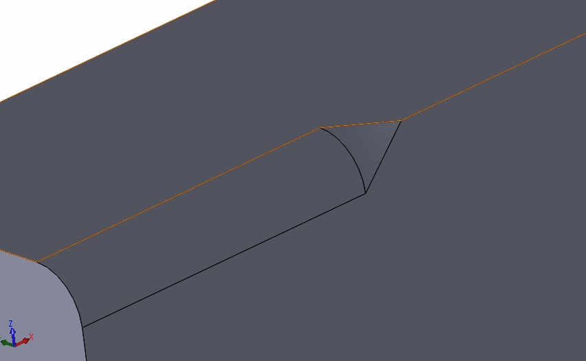
I'm pretty confident that this very closely matches the SW, based on how the SW was done and how I built it in Creo. Measuring the two surfaces, they seem very close:
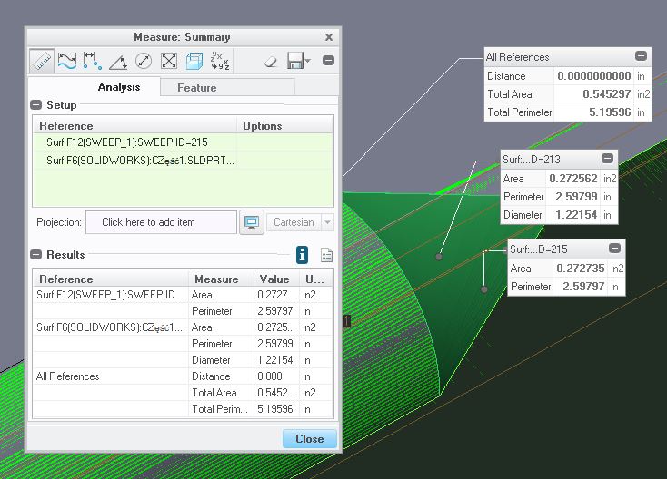
In the center of the top edge, the two edges are not perfectly coincident, but the difference is less than 0.0005" in the center. They are aligned at the ends.
Brian has a good point, we don't know why he's after this geometry, it could be there are better ways to accomplish his larger goals.
Mar 16, 2016
02:42 PM
- Mark as New
- Bookmark
- Subscribe
- Mute
- Subscribe to RSS Feed
- Permalink
- Notify Moderator
Please log in to access translation
Mar 16, 2016
02:42 PM
Rohit and Brian are creating basically the same shape. Rohit chose to include the round with his cut but the ending feature is the same where he could have minimized it some.
Again, I have a real interest in being able to accurately mimic real world conditions including true-to-intent replications. Everything else is an approximation.
If I was creating this from scratch, yes, the VSS solution is fairly straight forward. It is likely "close-enough", sure. That isn't my take on the OP's request.
Mar 16, 2016
01:06 PM
- Mark as New
- Bookmark
- Subscribe
- Mute
- Subscribe to RSS Feed
- Permalink
- Notify Moderator
Please log in to access translation
Mar 16, 2016
01:06 PM
We are just doing this to simulate the exact SW geometry, right? I mean... as a purely academic exercise? Did the original poster really need this exact, precise piece of geometry or was he just trying to do a simple round with a transition at the end? I'm just trying to understand for my own knowledge. The way I read the original poster's message, he's just saying "I can do this in SW as a sweep, can I do it in Creo, too?"
On the one hand, I was able to generate something exceptionally similar using "a simple round" with a variable radius and a transition. But I think it was hit on the head when he said "As always, it depends on the actual SHAPE you want." Are we just aiming for a round along part of an edge that tapers to a point? If so, mission accomplished in 15 seconds without a sweep, no trajpar, no complicated boundary conditions, and one simple(-ish) feature. But if we're actually trying to completely mimic this SW geometry, then I suppose understand this thread.
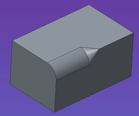
The SW geometry seems to have complete tangency nowhere along the triangular patch except at the edge where it intercepts the 15mm round. It surely isn't tangent along the two edges tapering into the point. On the Creo side (using the simple variable round), there's no tangency along that intercept edge - but there is tangency along the two edges. See below... (click for larger image).
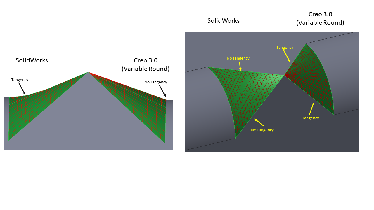
Or, perhaps I've just "lost the plot"?
Thanks!
-Brian
Mar 16, 2016
01:17 PM
- Mark as New
- Bookmark
- Subscribe
- Mute
- Subscribe to RSS Feed
- Permalink
- Notify Moderator
Please log in to access translation
Mar 16, 2016
01:17 PM
I was after duplication and posted the same question as to the requirements.
Personally, I find the geometry intriguing.
Mar 16, 2016
02:46 PM
- Mark as New
- Bookmark
- Subscribe
- Mute
- Subscribe to RSS Feed
- Permalink
- Notify Moderator
Please log in to access translation
Mar 16, 2016
02:46 PM
Have we completely exhausted all options using a regular sweep using Constant Normal Direction (the old "Pivot Dir" option) and other section plane control items? I was able to get some awfully close geometry using a single 2-point curve and some clever sketching. It's still not exact.
I guess I was just wondering if we were going down the rabbit hole because SW was genuinely doing something amazing that Creo cannot do. I don't think that's the case. I was just checking. It's certainly fun. 
Mar 16, 2016
02:53 PM
- Mark as New
- Bookmark
- Subscribe
- Mute
- Subscribe to RSS Feed
- Permalink
- Notify Moderator
Please log in to access translation
Mar 16, 2016
02:53 PM
Of course we jumped into the rabbit hole, Brian What are you thinking
I am confident that I can fully duplicate the SW geometry using a different method.
The secrets hidden in boundary blend are pretty logical in that sense.
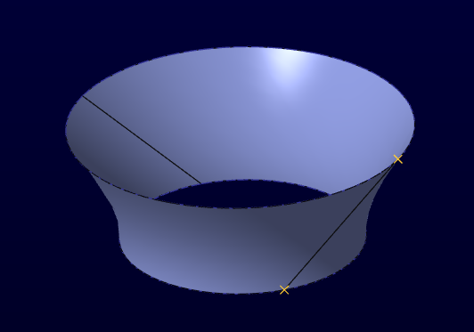
The "duct" above is a very straight forward way of twisting the surface 45 degrees to obtain the tangent.
None of this was obvious (to me) until you spend a little time trying to unravel this.
Mar 16, 2016
02:59 PM
- Mark as New
- Bookmark
- Subscribe
- Mute
- Subscribe to RSS Feed
- Permalink
- Notify Moderator
Please log in to access translation
Mar 16, 2016
02:59 PM
PS: What SW does is not necessarily amazing... it is more like befuddling.
When you create a helical cut, it automatically does the "reverse cut" as well.
When you extrude-cut a hex into a pilot-drilled cap screw head until the drill point edge, it automatically merges the coned floor into the new cut.
I didn't ask for that but it has no option to not do that. I can see how someone would like that, but what if you didn't want that?
In general, what you think you told SW to do, it does an approximation.
And for 3D sketching, it is a nightmare because the solver in SW sucks in comparison to Creo.
We never liked PTC telling us what to do by locking out options. But at least PTC is always true to the input regardless of how illogical it may seem.


