Community Tip - Did you get called away in the middle of writing a post? Don't worry you can find your unfinished post later in the Drafts section of your profile page. X
- Community
- Creo+ and Creo Parametric
- 3D Part & Assembly Design
- Re: toothed belt clamp
- Subscribe to RSS Feed
- Mark Topic as New
- Mark Topic as Read
- Float this Topic for Current User
- Bookmark
- Subscribe
- Mute
- Printer Friendly Page
toothed belt clamp
- Mark as New
- Bookmark
- Subscribe
- Mute
- Subscribe to RSS Feed
- Permalink
- Notify Moderator
toothed belt clamp
Hi,
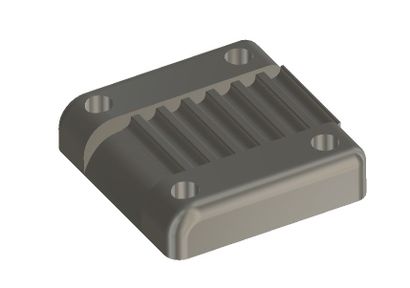
I'd like to create a clamp that holds an toothed belt in place. Here you can see an example:
I created this example using another CAD-System. Now I want to create the same (negative) HTD-5M-profile in Creo, with the difference, that the profile has to start at the beginning of the part.
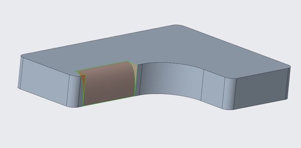
I created my holding-plate and removed some material (using a spline and two straight lines):
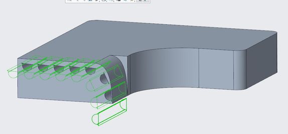
Then I created a sketch of the HTD-5M-belt, extruded it and patterned the extrusion along a curve. The result looks like this (with activtated sectional view):
So something went wrong. Is this the right way to do it ? How would you do it ?
A sketch of the HTD-5M-Profile can be found here:
https://capolight.files.wordpress.com/2018/06/489bd-5m.jpg?w=640
Maybe someone can make a short video on how to do this ?
Thanks,
Maik
- Labels:
-
General
- Mark as New
- Bookmark
- Subscribe
- Mute
- Subscribe to RSS Feed
- Permalink
- Notify Moderator
Your general approach seems valid. There are other options to get this done, design intent may come into play. Merge cut-out function could achieve this readily if you have a model of the belt already along the path. This would cut out the geometry of the belt from the block in a single feature.
If you would include your model or at least the details of the pattern leader including the sketch and the pattern properties that will help others figure this out.
It appears to me that your extruded cut for the tooth profile is not removing material from the clamp block. I can not tell why without seeing the sketch etc.
Involute Development, LLC
Consulting Engineers
Specialists in Creo Parametric
- Mark as New
- Bookmark
- Subscribe
- Mute
- Subscribe to RSS Feed
- Permalink
- Notify Moderator
yes, the pitch will change each time it travels over a curve. This works the same on the airport conveyor, some segments need to shrink when it turns. Not sure how you want it to be in this case.
In my model, I keep the sketched distance the same but it gets smaller after cut due to the overlapping of adjacent sections.
- Mark as New
- Bookmark
- Subscribe
- Mute
- Subscribe to RSS Feed
- Permalink
- Notify Moderator
@BHOoi :
Thanks. I think your solution is what I need.
I looked at your solution that looks very nice and have one question: why do you use two sketches in the group that is patterned ? Would it also work with one sketch only ?
I tried to create the part myself, but there is an error when I pattern the group. As long as the curve is a straight line everything works fine, but when the curve is bent then the sketches fail. So maybe i made a mistake in the sketch.
Maybe you have an idea what i did wrong ?
Thanks,
Maik
- Mark as New
- Bookmark
- Subscribe
- Mute
- Subscribe to RSS Feed
- Permalink
- Notify Moderator
Hi,
1. yes, it may work as well if all features are grouped in a single group. I normally like to separate the merge as I found this way is easier to manage if failure happens.
2. The tricky part of this exercise is at corner where the sketched section may fail due to invalid constraints. In my model, I used points to control the absolute distance. The distance stays the same regardless where the points lie either on a straight line or curve.
3. When you create your section, always ensure all the constraints will remain valid even when it is on the curve. It's good to create your start your first section on the curve. Watch out for horizontal/vertical constraints that might fail when the direction changes.
I am still on Creo 4 and unable to open files from higher versions. If you can send me your file on Creo 4 or lower, i can take a look what went wrong.
- Mark as New
- Bookmark
- Subscribe
- Mute
- Subscribe to RSS Feed
- Permalink
- Notify Moderator
I tried and my model turned up like below:
One thing to note is that the pitch might not be right at the corner area. I attached creo4 file here hope it serves some help to you.
- Mark as New
- Bookmark
- Subscribe
- Mute
- Subscribe to RSS Feed
- Permalink
- Notify Moderator
Hi,
Thanks for your replies.
@tbraxton: In BHOois-project you can find a sketch of the HTD-5M belt (and in my first post of this thread).
@BHOoi : That looks good, but the pitch is very important because the part is going to be manufactured and actually really clamps a belt.
And when I think about it: Doesn't the pitch of a belt get smaller when it its bend ? The tooth get closer to each other when the belt is bend. So maybe your solution is right ?
I also tried to do it with another technique. In my case the pitch seems to get larger.... You can see my approach in the file attatched.


